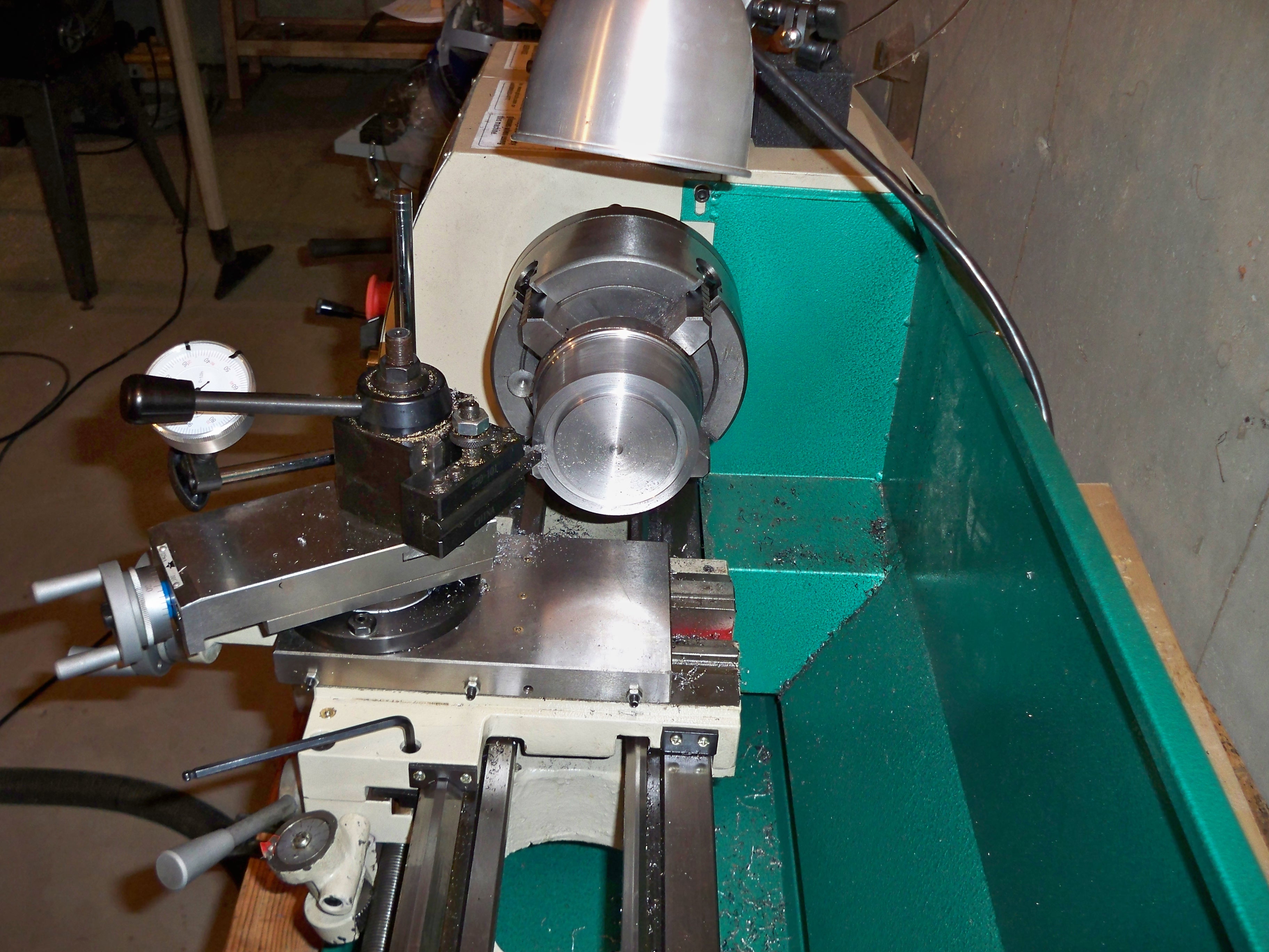
2/22/2011: This is the start of the ball turning attachment. I am modeling it after Steve Bedair’s Ball Turning Tool Post at http://www.bedair.org/Ball/ball.html . There is one problem, my G0602 does not have a T-Slotted cross slide. I contacted Grizzly and they said that the T-Slotted cross slides are on Backorder until April 4th, 2011. I have decided to experiment and see what I can do with the existing toolpost and cross slide. See Photo below…
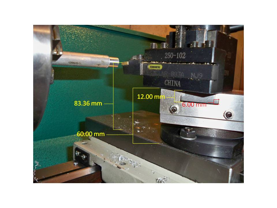
There is not a whole lot of space between the tool tip and the top of the cross slide. I want to make a > or = 2 inch ball turner but there is not enough space between the top of the compound slide and the tip of the tool. So I will make two different different ball turning attachments; one tool post for small balls and one attachment for > 2 inch balls.
2/22/2011 8:30pm I went to Interstate Metal and Alloy today and picked up a couple of pieces of steel. One 4″ diameter x 3″ long and two 2.25″ diameter by 2″ long pieces and a 1/2″ thick odd shaped piece of aluminum; not shown …
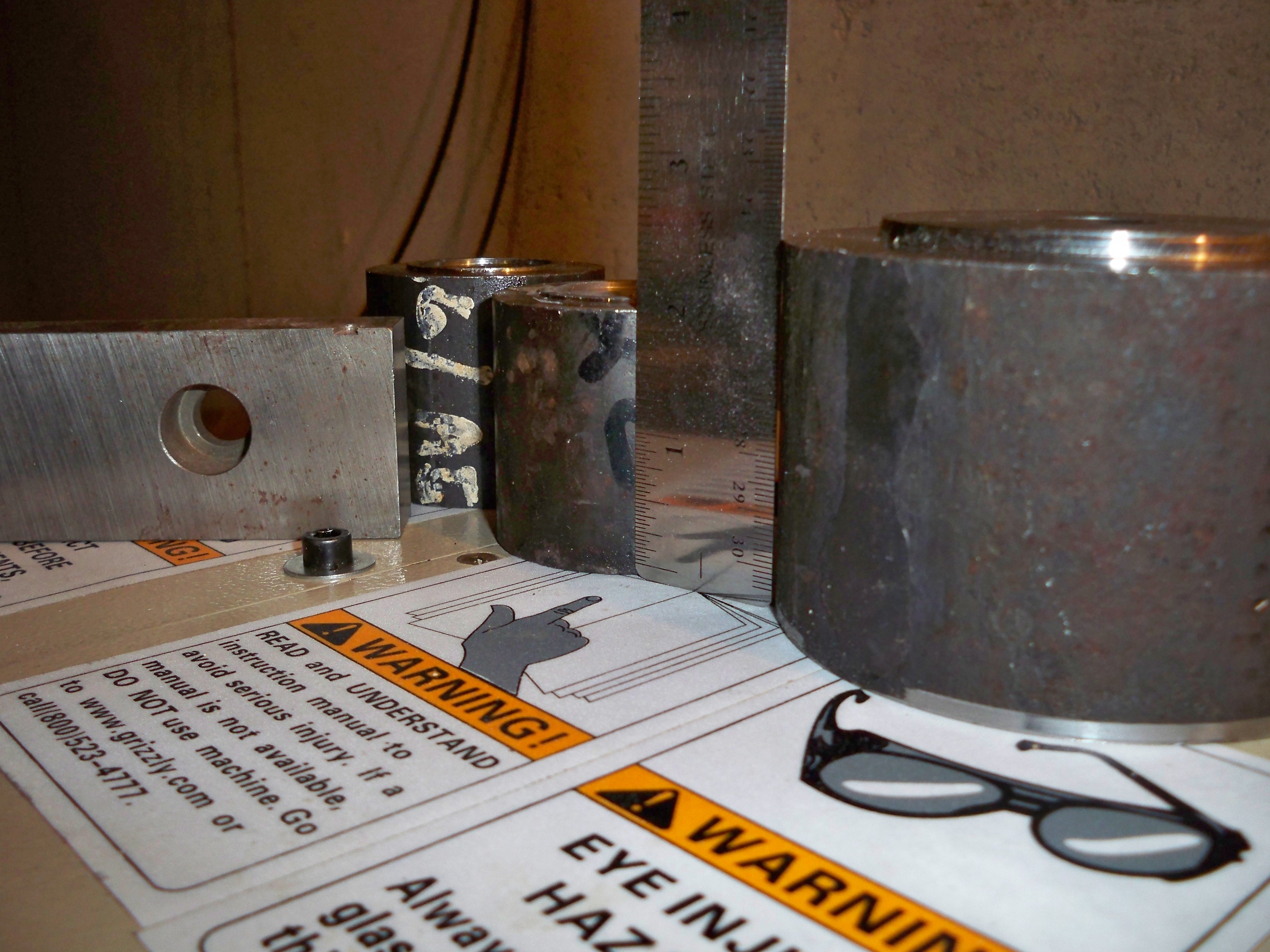
…the 1/2″ piece of steel that I had on the left I already had. It might be interesting to use the 4″ diameter piece for the part that turns. It is heavy and may result in less chatter…???…maybe. I am stopping by Interstate Metal and Alloy tomorrow to see if they have another. I arrived at closing and they let me look around anyways while they cleaned up and I found one without digging too much.

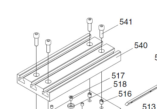
I decided that I will add the G0516 mill table to my cross slide ($46.45 delivered with screws). It will require that I bore and tap 4 holes in the cross slide but it will provide a better platform for the 2″ ball turner. I ordered 4each p0516541’s and 1 each p0516540.
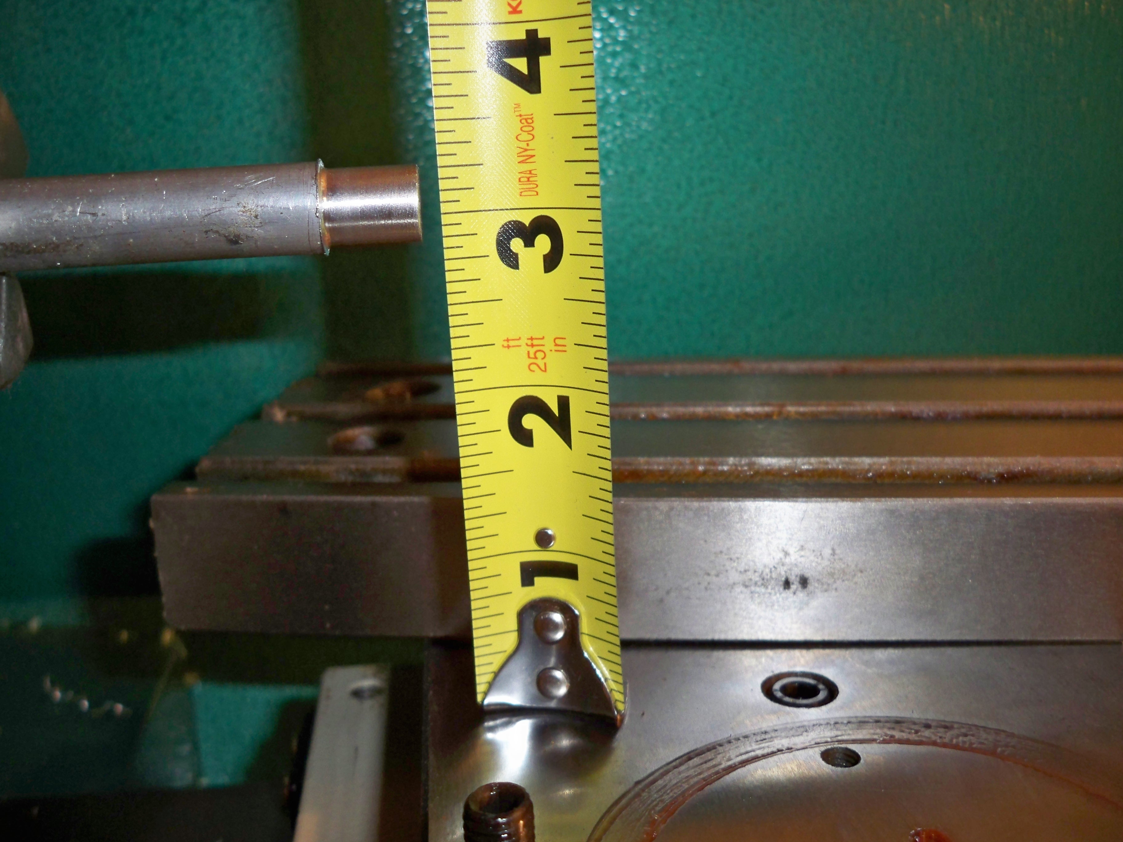
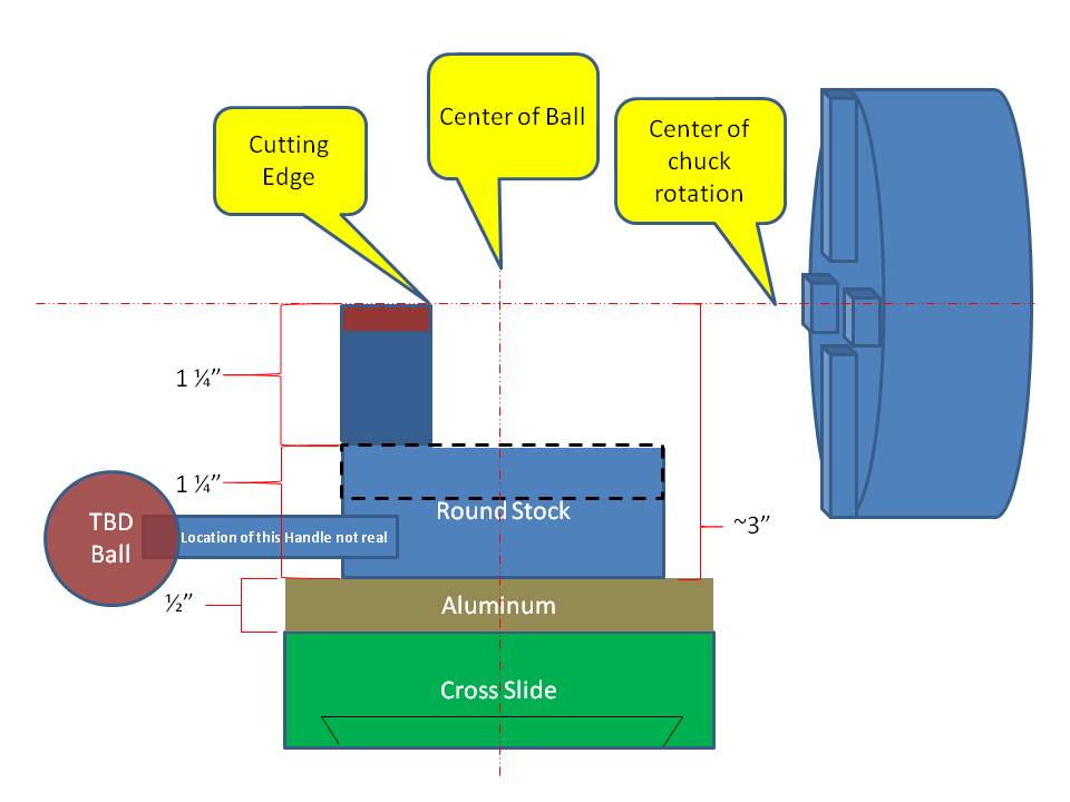
3/1/2011…I received the mill table yesterday and found that it is going to be great for a lot of projects. For the >2″ ball turning tool the table top takes too much vertical space. There is only ~3 inches between the center of the chuck and the top of the cross slide.
I am investigating and considering an “Up and Over” version of the ball turning tool; where the rotational axis of the tool is in parallel and along the axis of the cross slide…. reference the following link…
http://www.haythornthwaite.com/ball%20turning.html
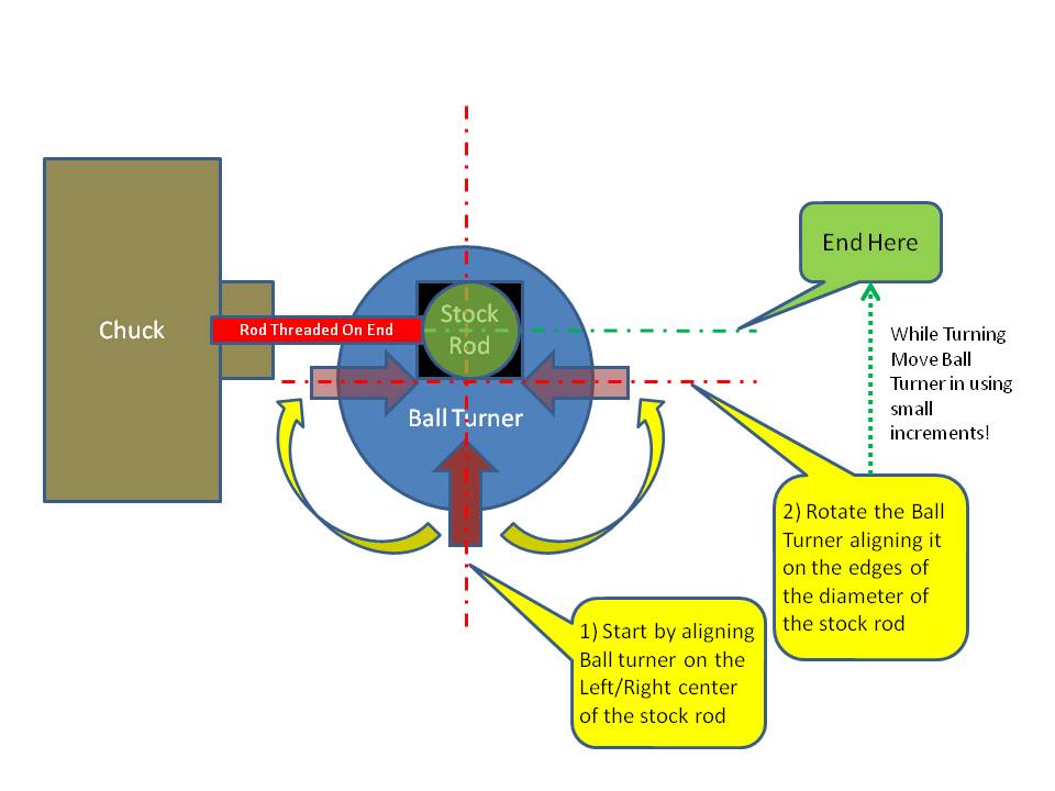
3/1/2011…I have created a powerpoint of the latest idea; I hope it makes sense…
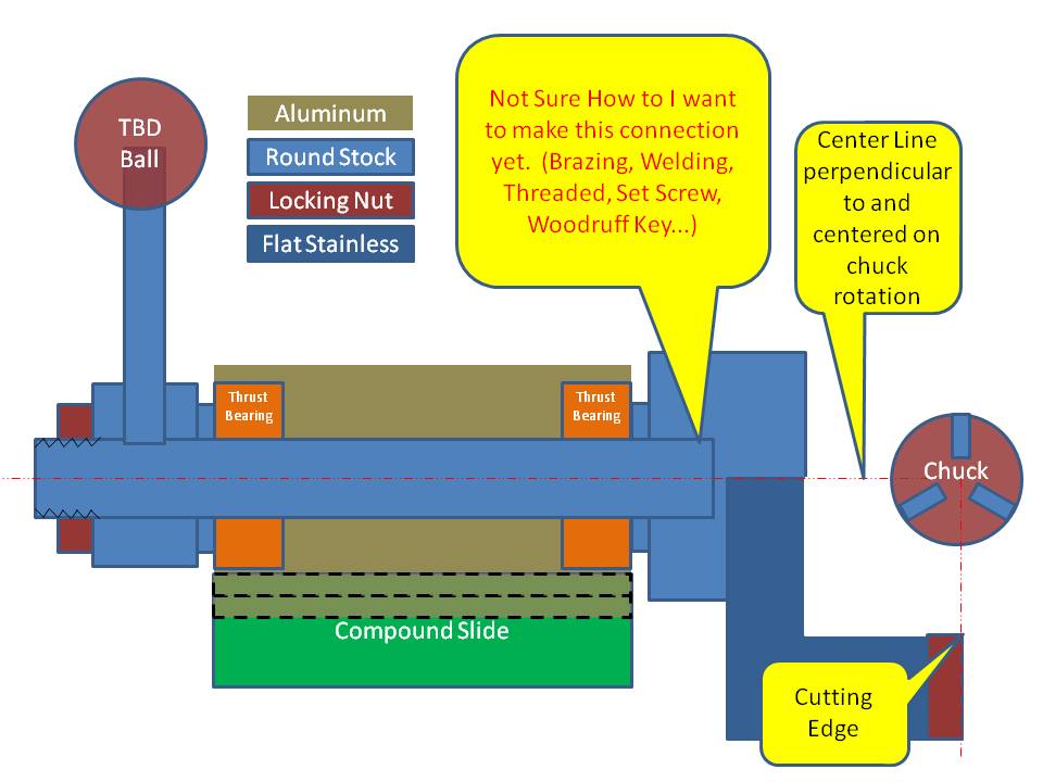
I am looking for ideas on how to secure the head. I really don’t want to machine it out of one piece of stock.
Steve Bedair’s design will work up to a ~2.5 inch ball but you have to remove the compound slide….
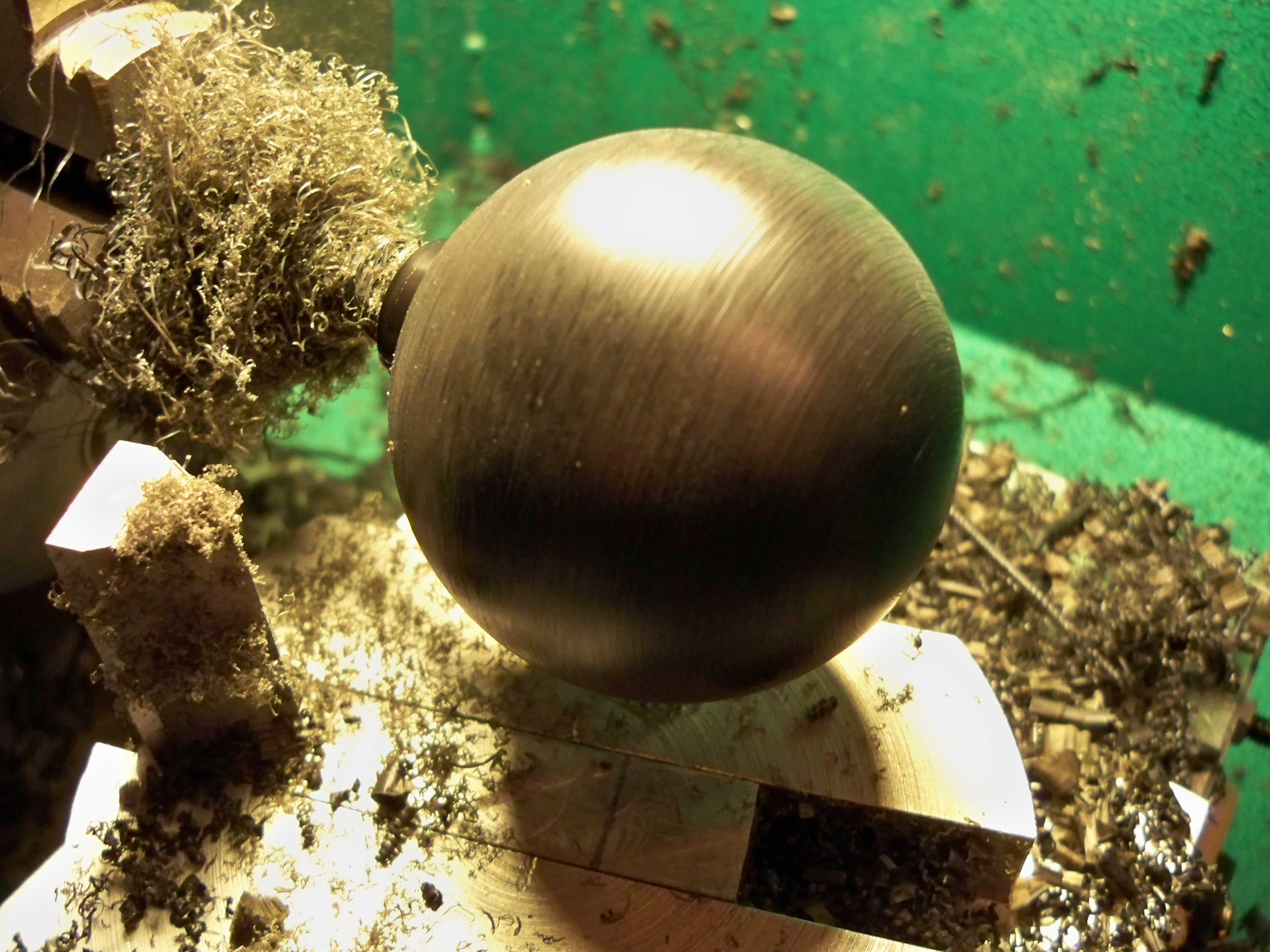
3/3/2011…I started to turn Steve’s version… I am using scrap which can be quite the learning experience. Cutting aluminum is always exciting. Turning an unknown metal of a large diameter can be even more exciting. I was told that the metal I am using is hot rolled steel; it has a fair amount of carbon which makes for a scruffy finish ( A highly technical term for… see the picture)…
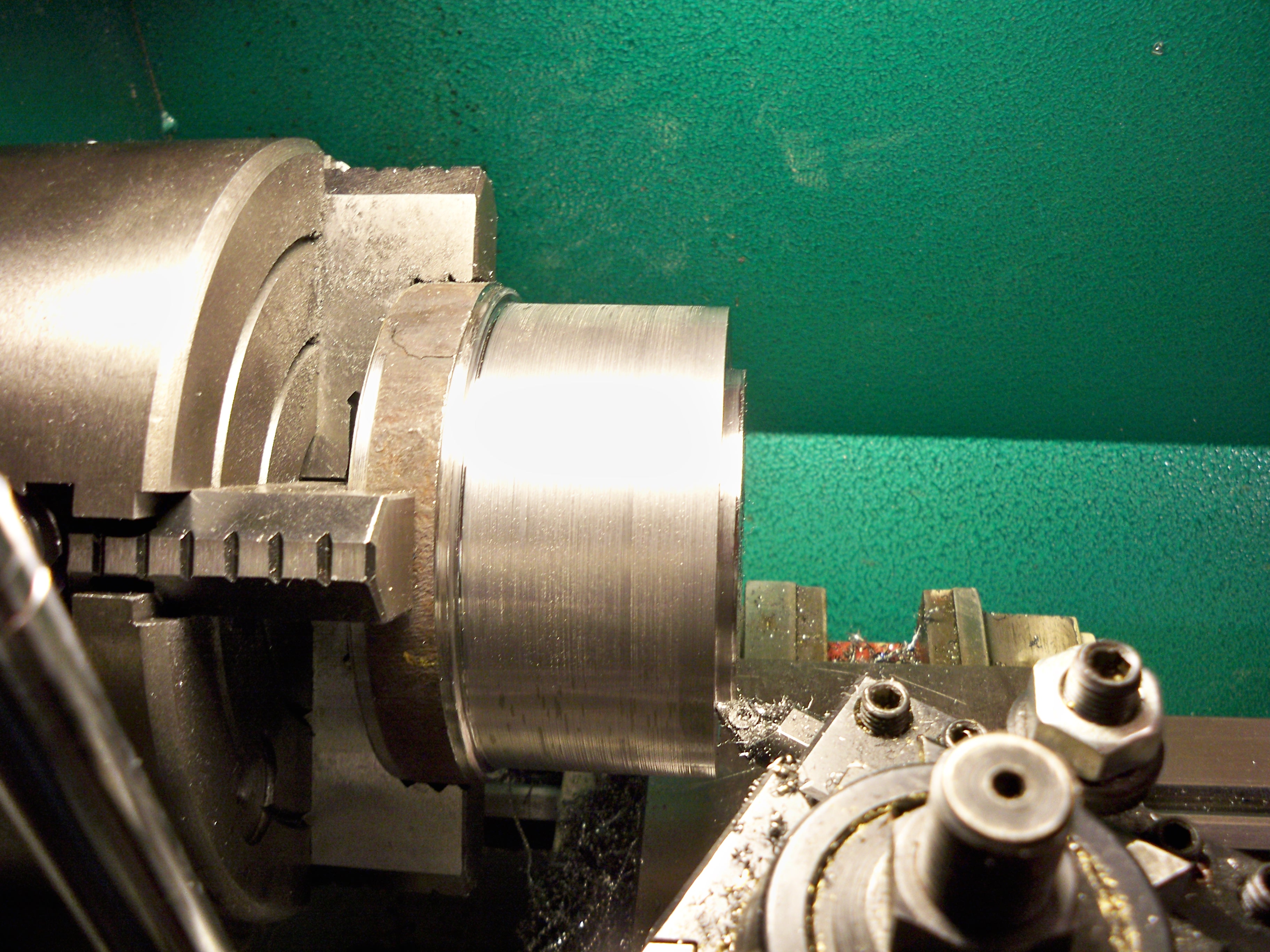
…Steve stated on his site…
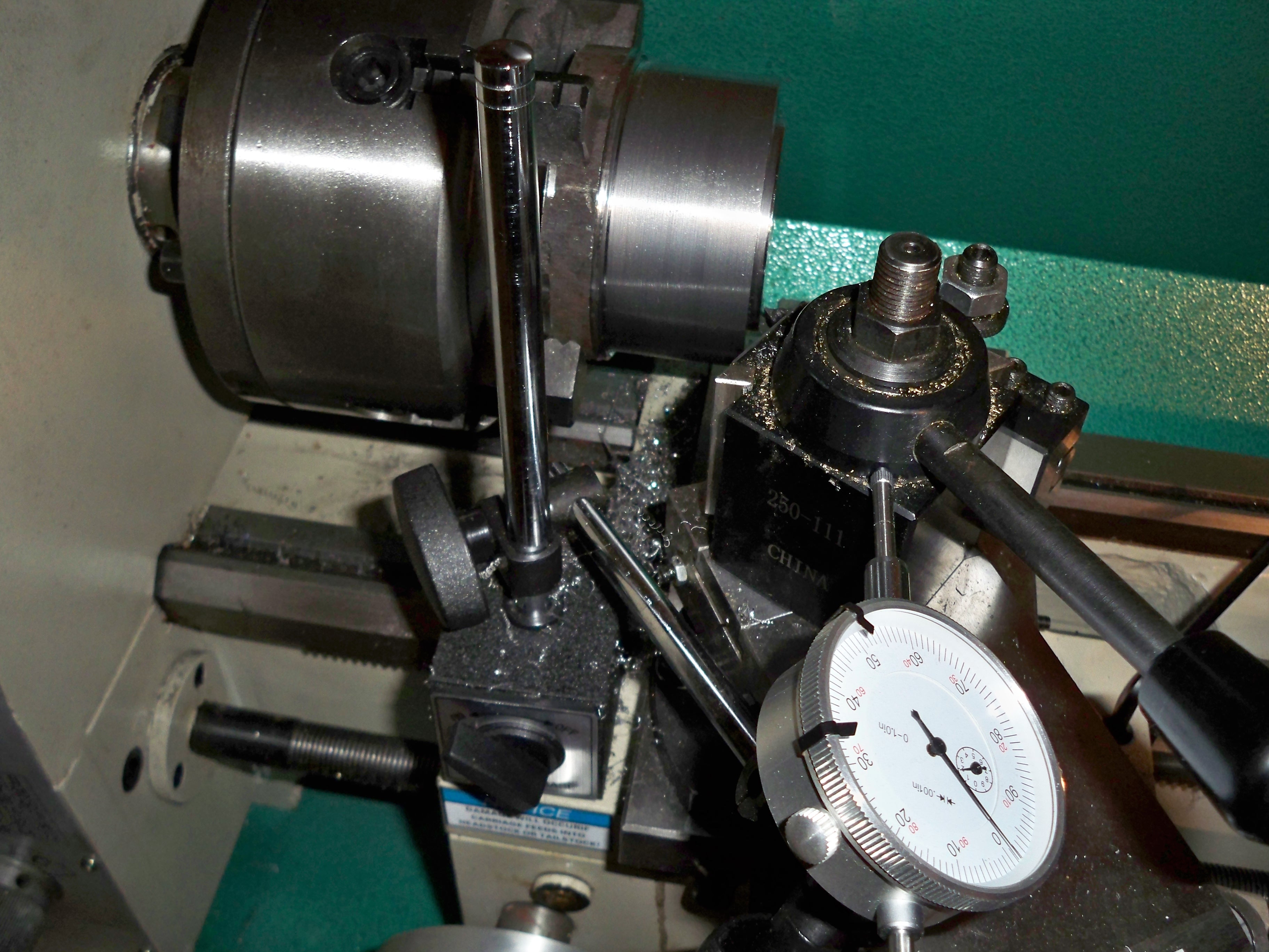
“…There is only one critical measurement , the cutting tool bit height.” . Well don’t forget to match the center hub of the Tool Holder to the Base. The O.D. of the Tool Holder isn’t critical so I played around with the finish of the prototype so the O.D. ended up at 3.716″. The hub of the Tool Holder I wanted to make more precise so I used a dial gauge and turned it down to 3.740″ with a .20″ wide x .01″ deep grease channel . I guess that the steel was low carbon because the chips curled nicely at 150 RPMs ~ 150 SFM. See below…
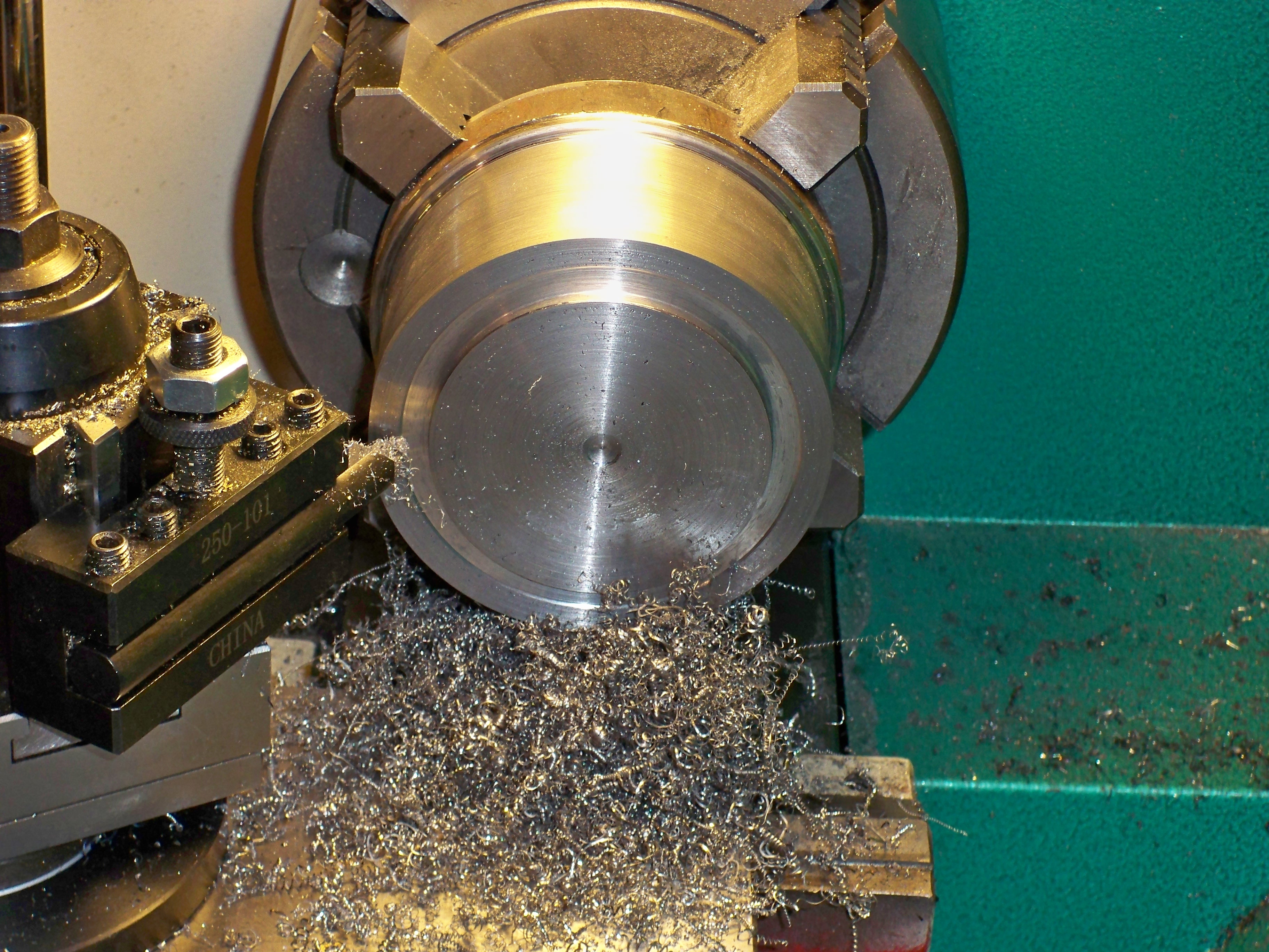
…The dial gauge was held magnetically to the base of the cross slide and made contact with the tool holder so I could measure the tool travel if I turn handle on the cross slide or if I turned the handle on the compound slide. …
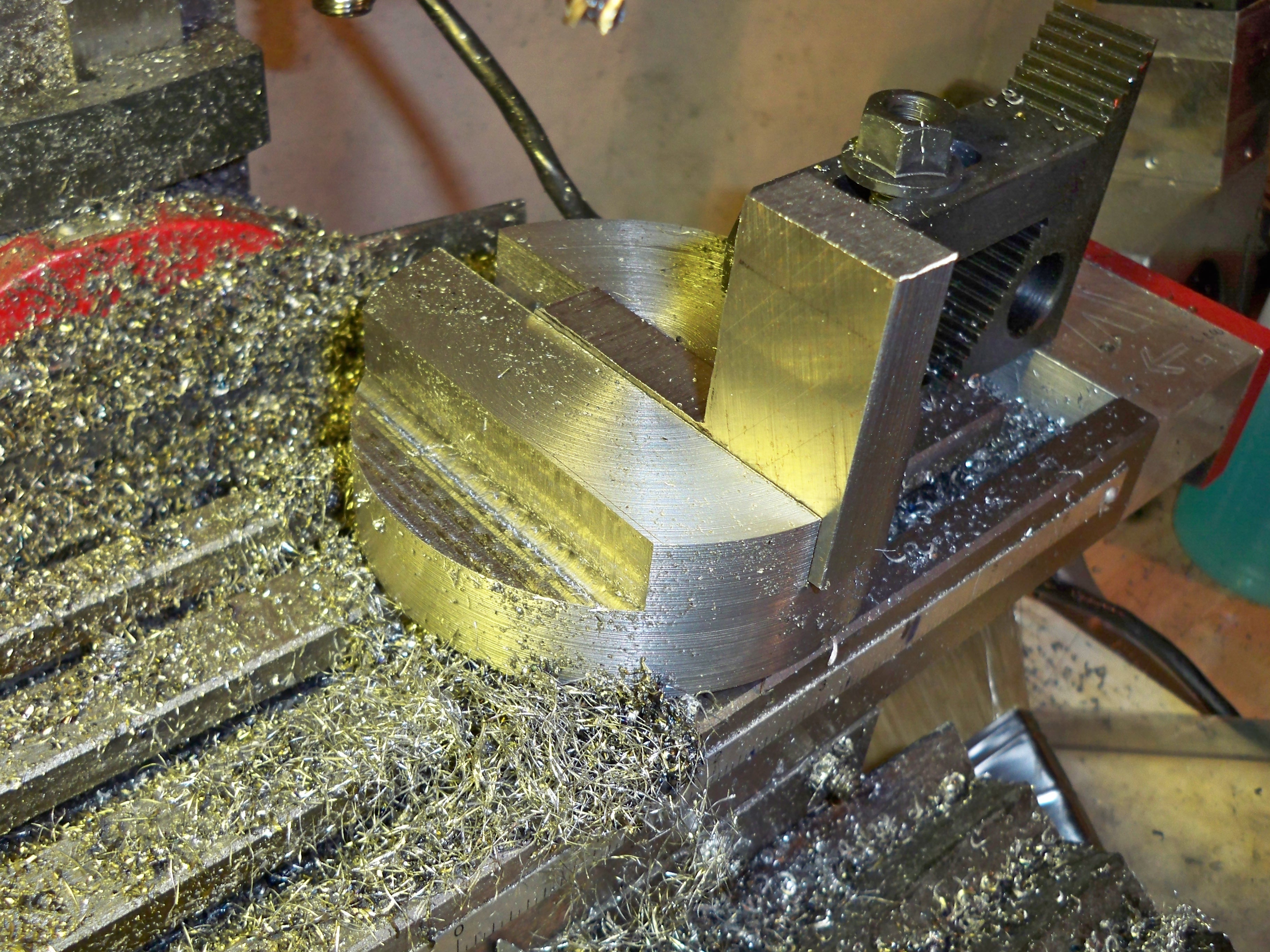
3/6/2011…I tapped the hub of the tool holder 3/8-16 about .625″ deep. Using the liquid cooled bandsaw and the milling table and a couple of really strong locking magnets I cut the hub to its approximate final thickness of 1.25″…
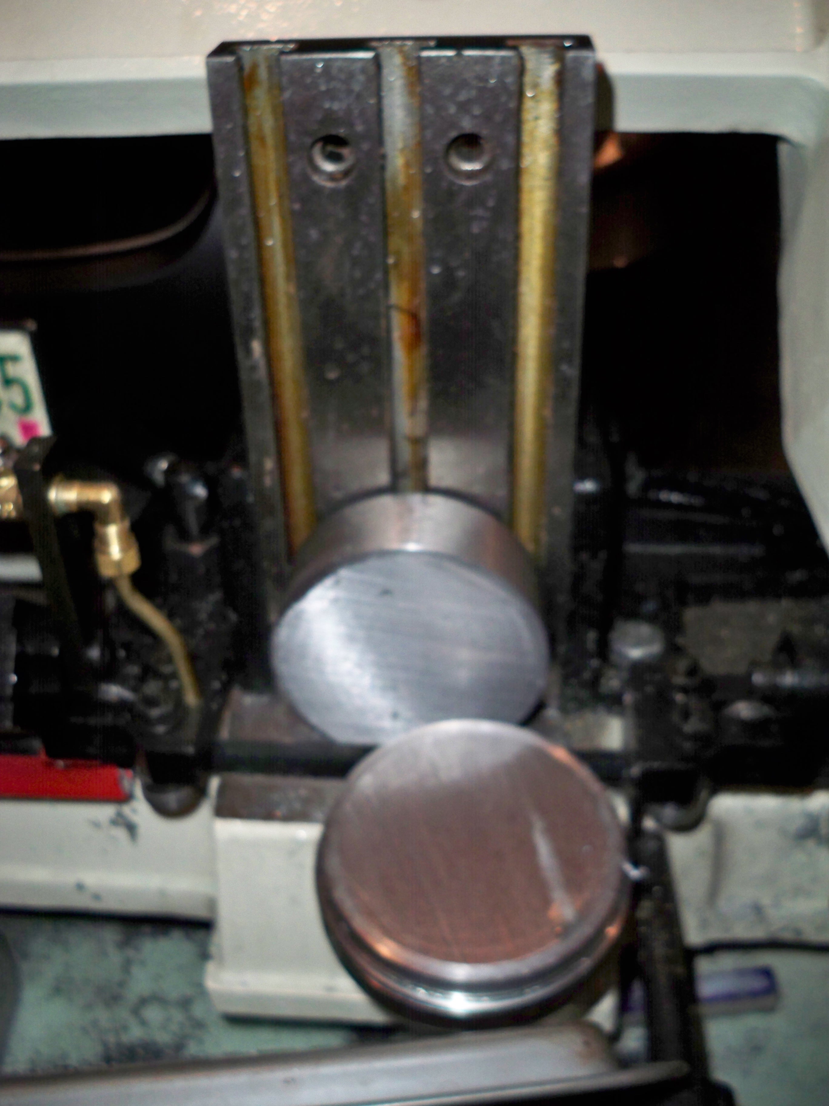
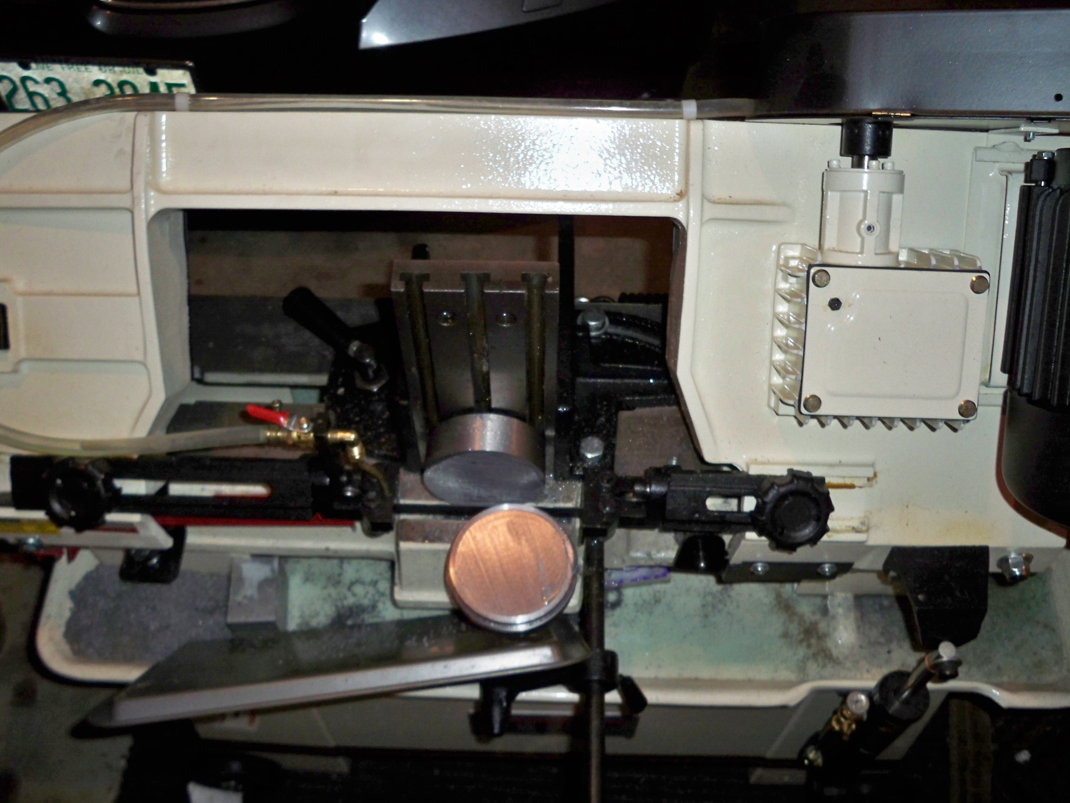
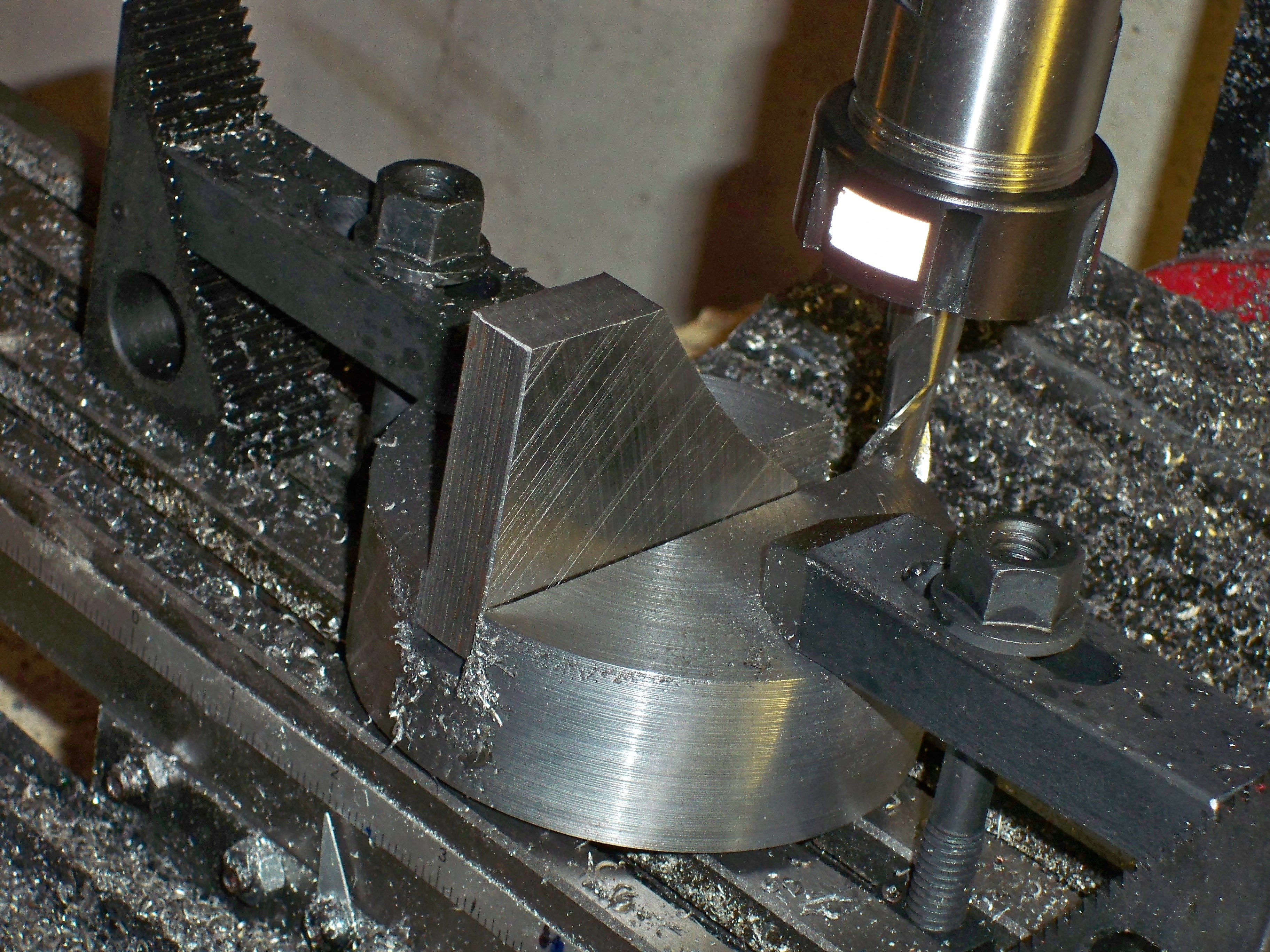
…I milled the slot and a flat on the Tool Holder Hub just to make it easier to drill the holes for the screws that hold the tool. Yes, I know that I should not have passed back through the swarf on the return pass because it is bad for the tool and not good for the finish. I used a roughing end mill and pencilled in the corners with a 1/4″ 4 Flute carbide end mill. What you don’t see in the video is that I used some 3/8-16 all thread to further attach the Tool Holder Hub to the milling table. This worked out great because I used a Coaxial Centering indicator to find the dead center before cutting the slot. (http://www.littlemachineshop.com/products/product_view.php?ProductID=2060&category=). Then I clamped the Tool Holder Hub to the milling table and locked the X-Axis and cut the slot. Locking the unused axis is always a good idea when not under CNC control.
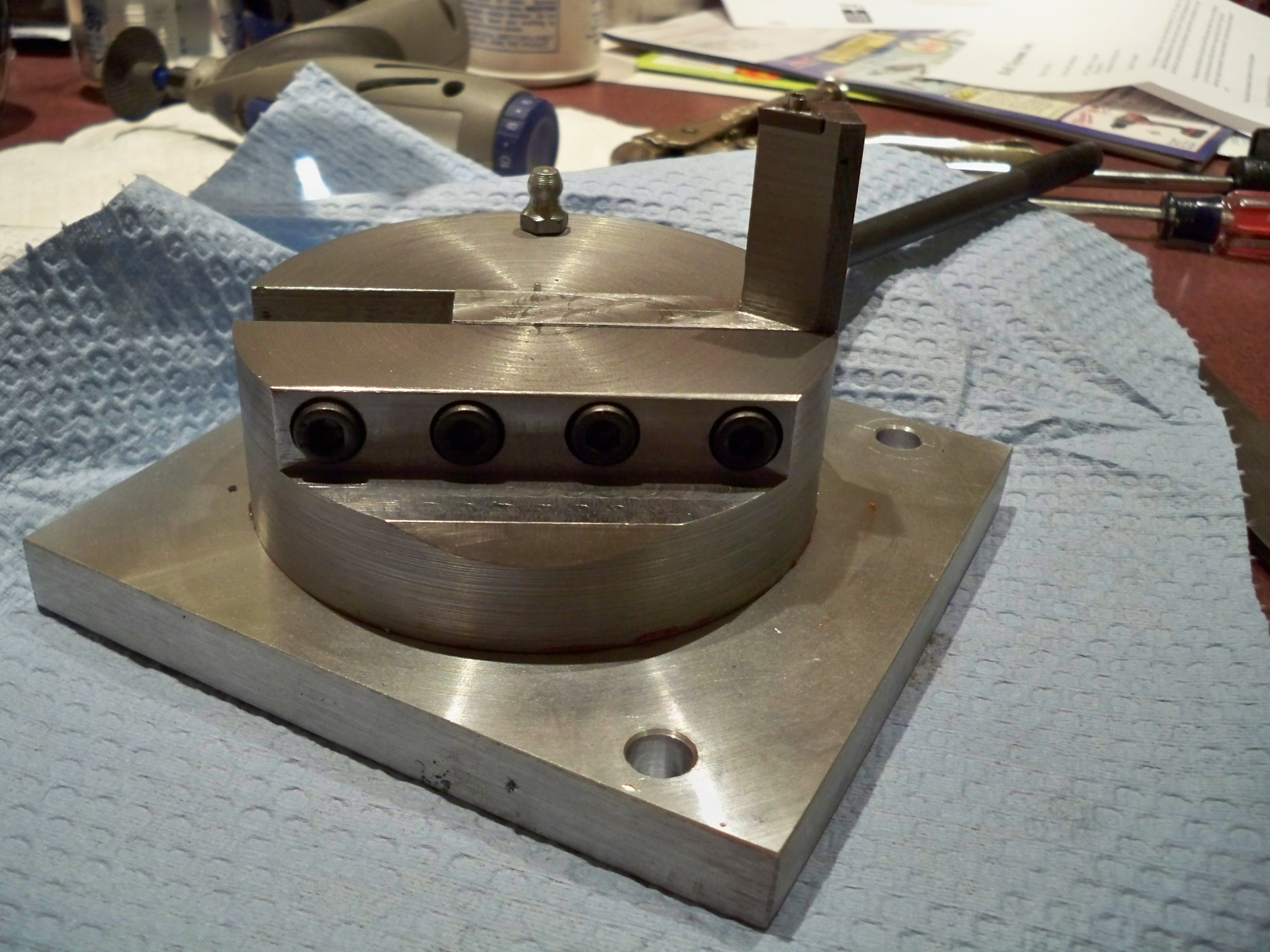
3/9/2011…I squared up the Tool Post and drilled, counter bored and tapped the Tool Post Holder. Four 1/4-20 x 1 inch long socketed hex cap screws were used. A 3″ machine vise was used to hold the Tool Post Holder during drilling an tapping. I also added a zerk fitting that I think Burt Rosensweig added to his; this means you don’t have to remove the Tool Post Holder from the base plate to lubricate the mechanism….
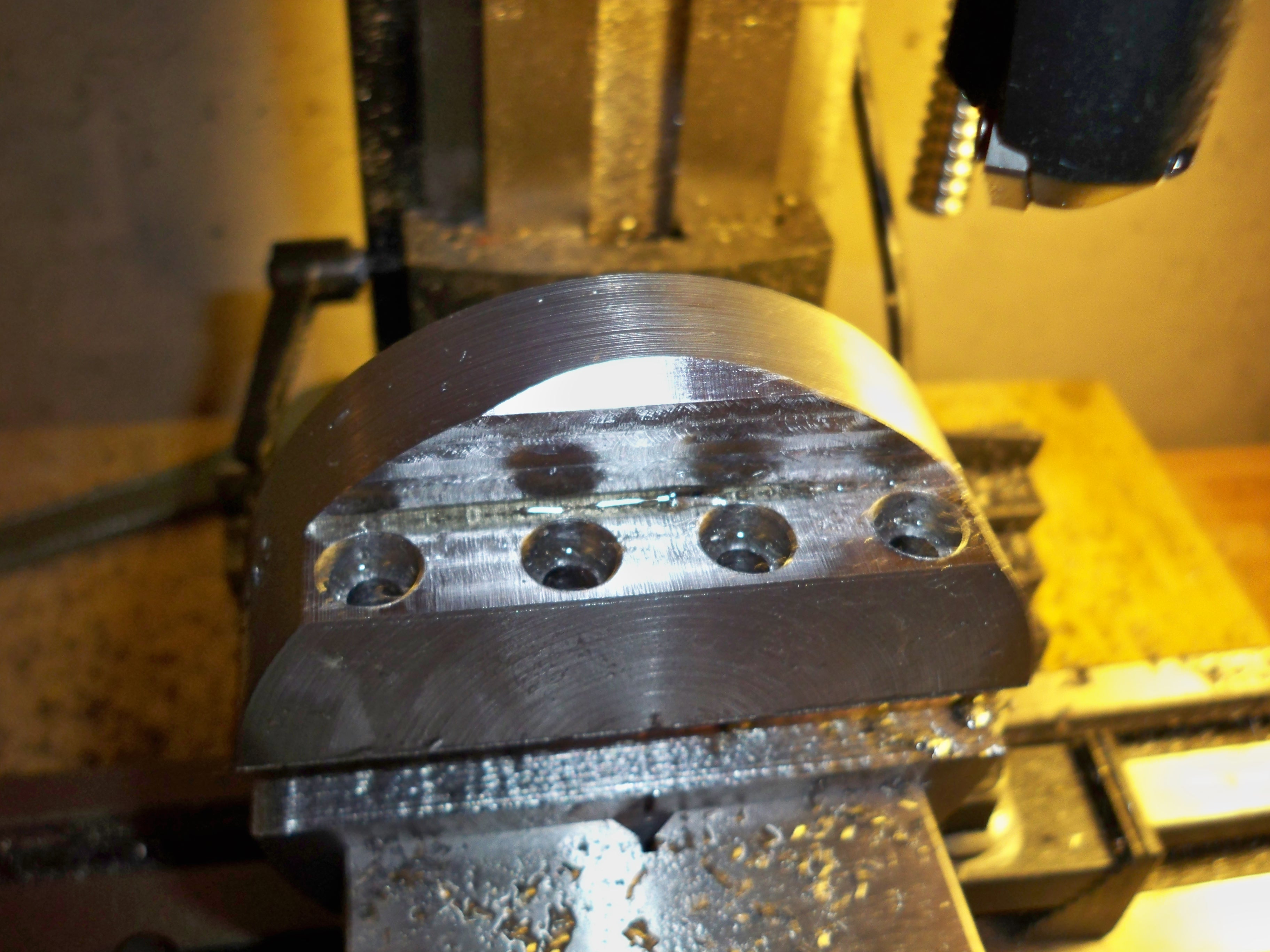
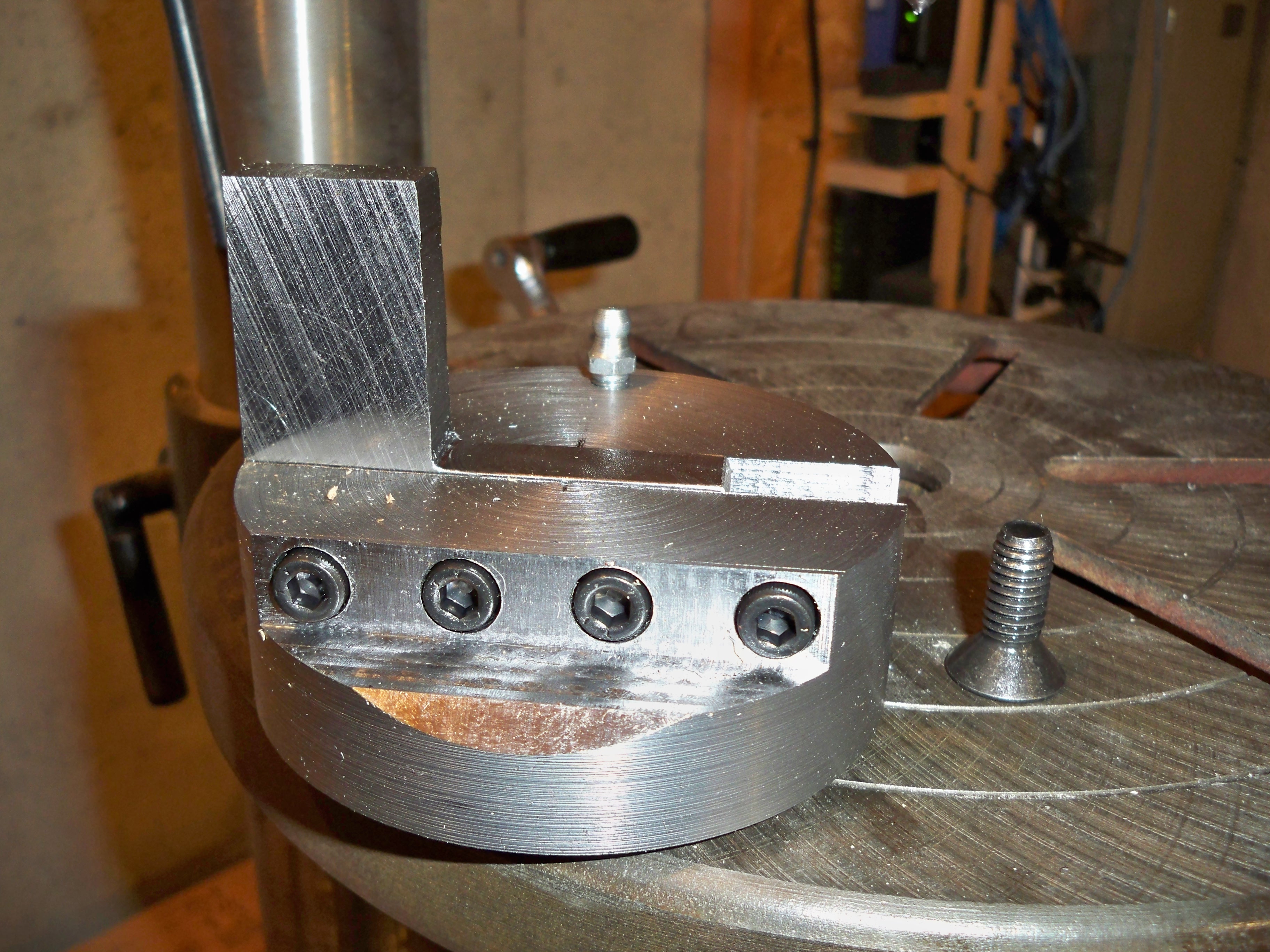
I have to make the base and finish making the tool. I plan on using two TMCT 21.51 triangular carbide indexes. I might finish it tomorrow. If not it won’t be until next week.
3/10/2011…I machined the Base Plate tonight from a piece of 1/2 aluminum…
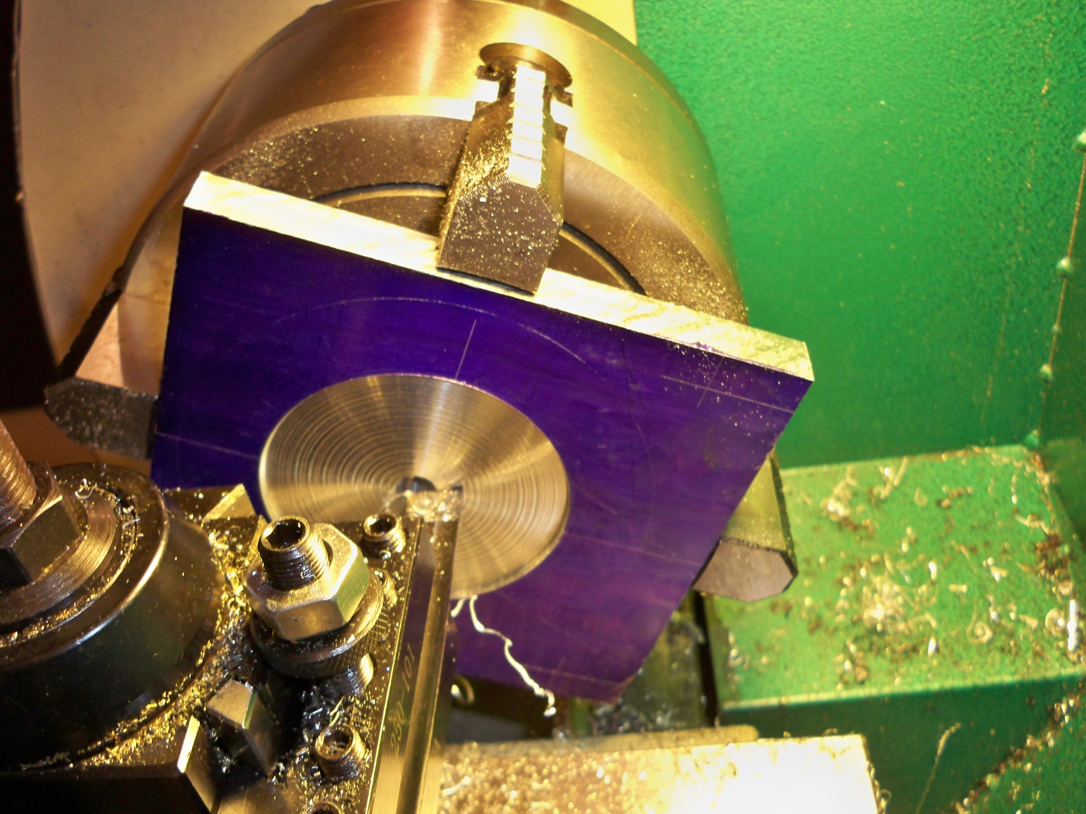
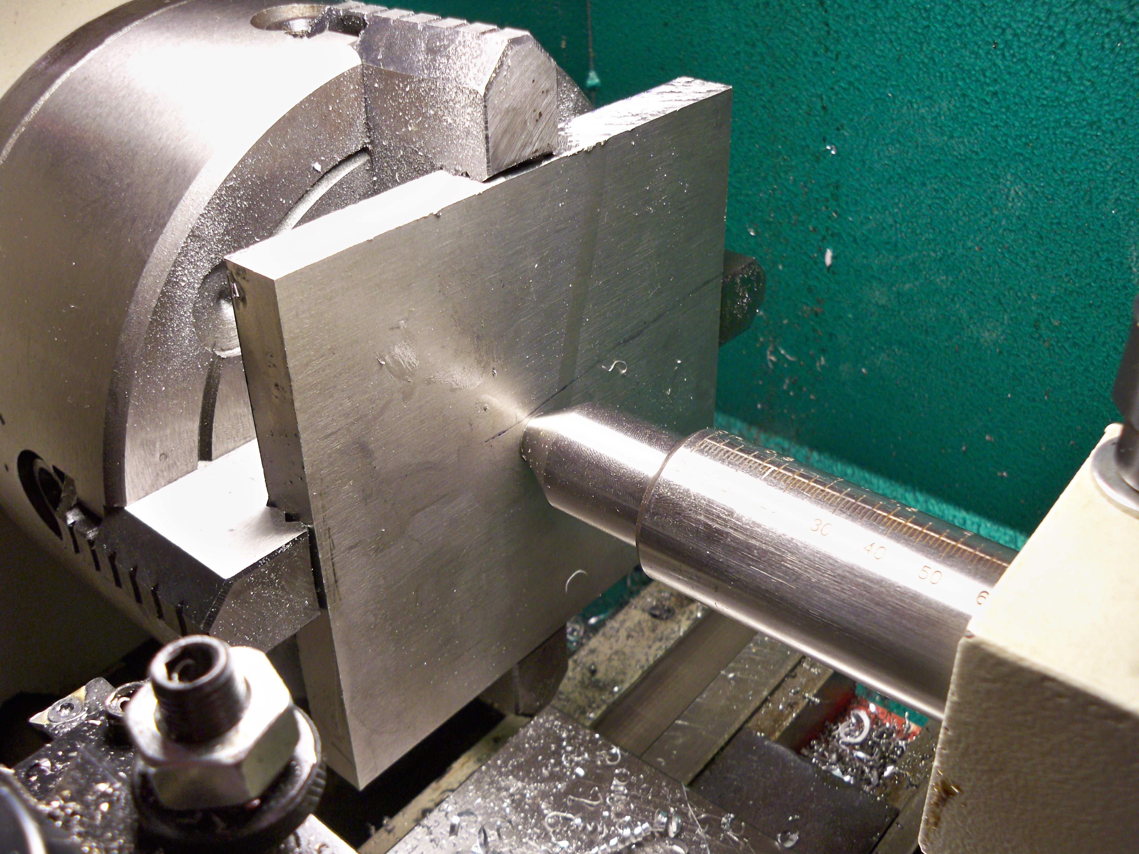
After machining the recessed area I flipped the plate over and used the dead center to align the plate in the chuck. I then countersunk the hole so that the 3/8-16 flathead screw would below the surface.
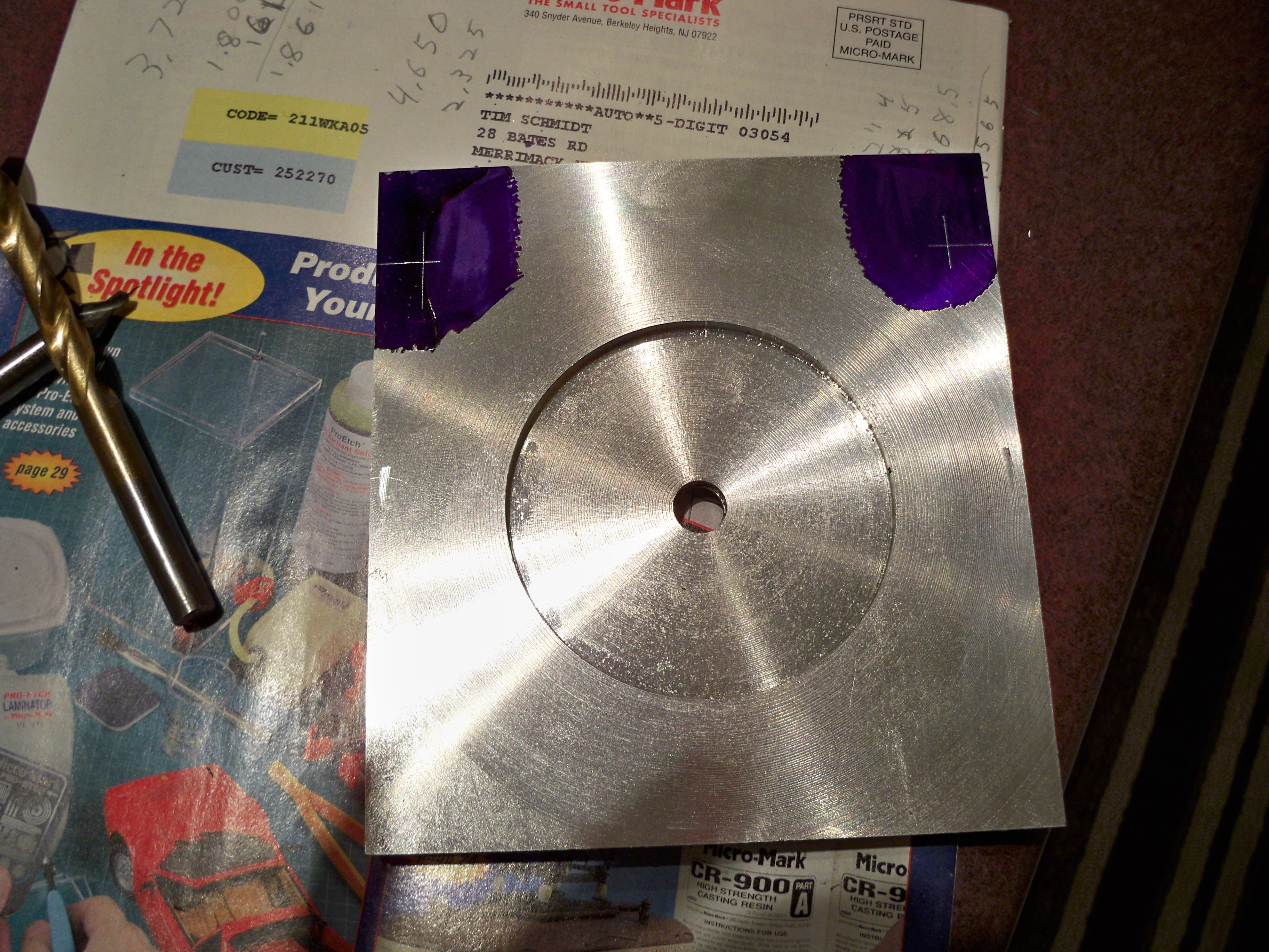
I marked the holes that hold the Base Plate to the Cross Slide. They are 50mm off of the center line through the hole used to mount the Tool Holder Hub and 20mm off of the end of the plate.
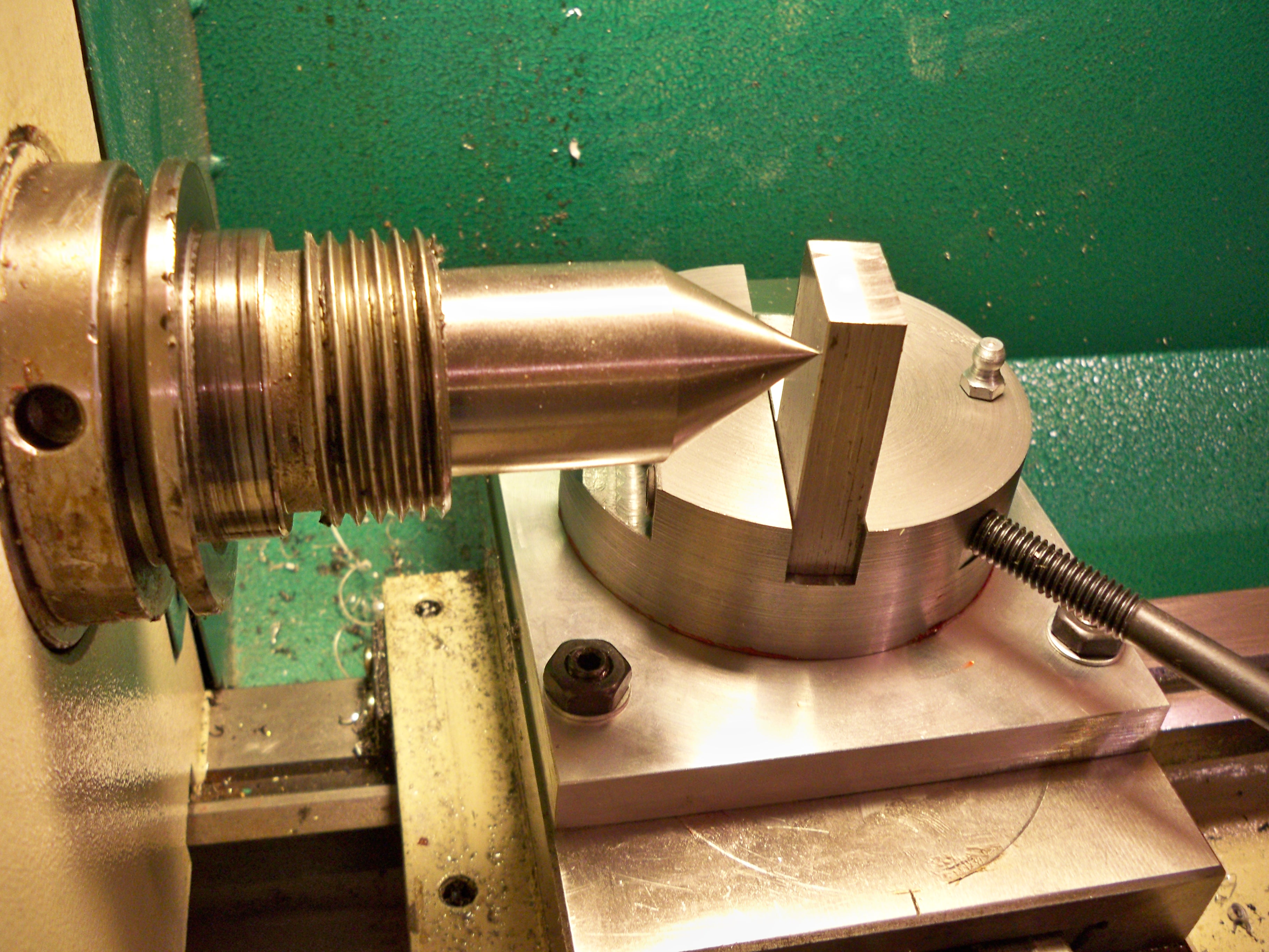
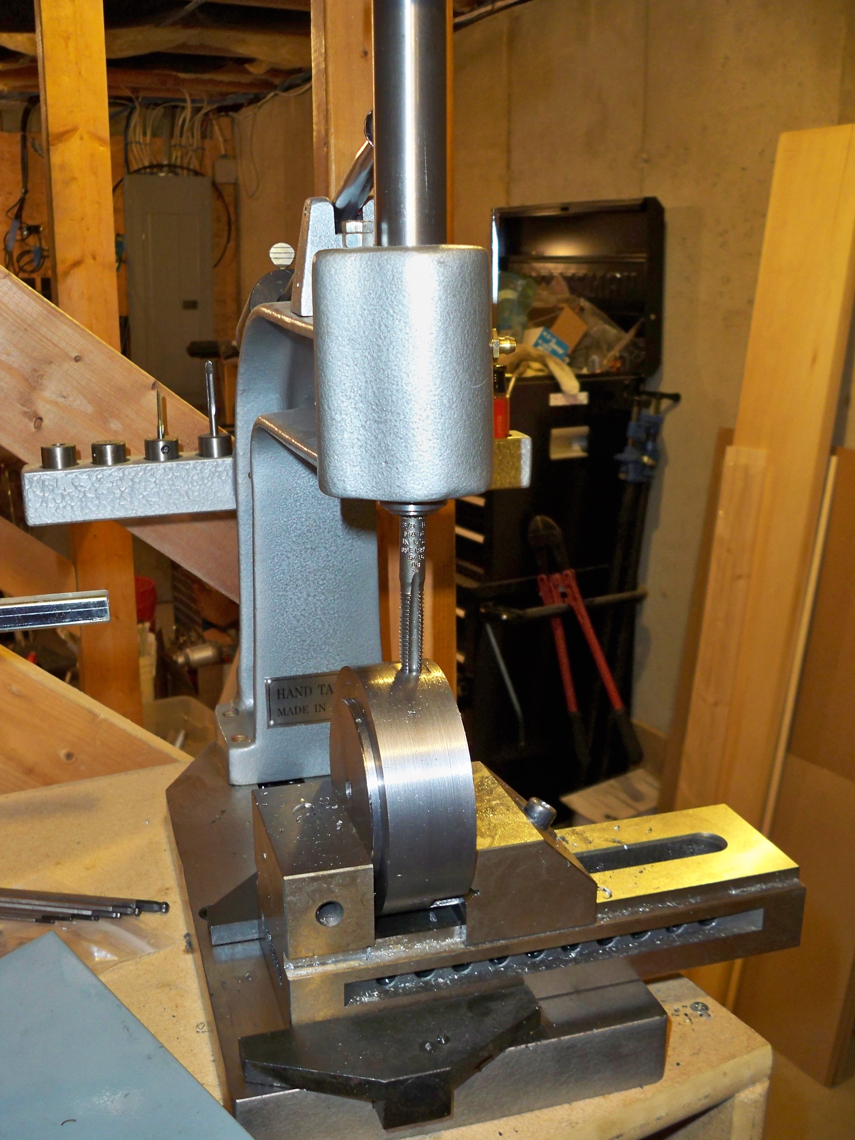
After cleaning everything up I mounted the Tool to the Tool Holder Hub and the Tool Holder Hub to the Base Plate; I then mounted the whole assemble to the Cross Slide using the existing hardware. After removing the chuck I place a dead center in the spindle; checked it for runout and marked the Tool…
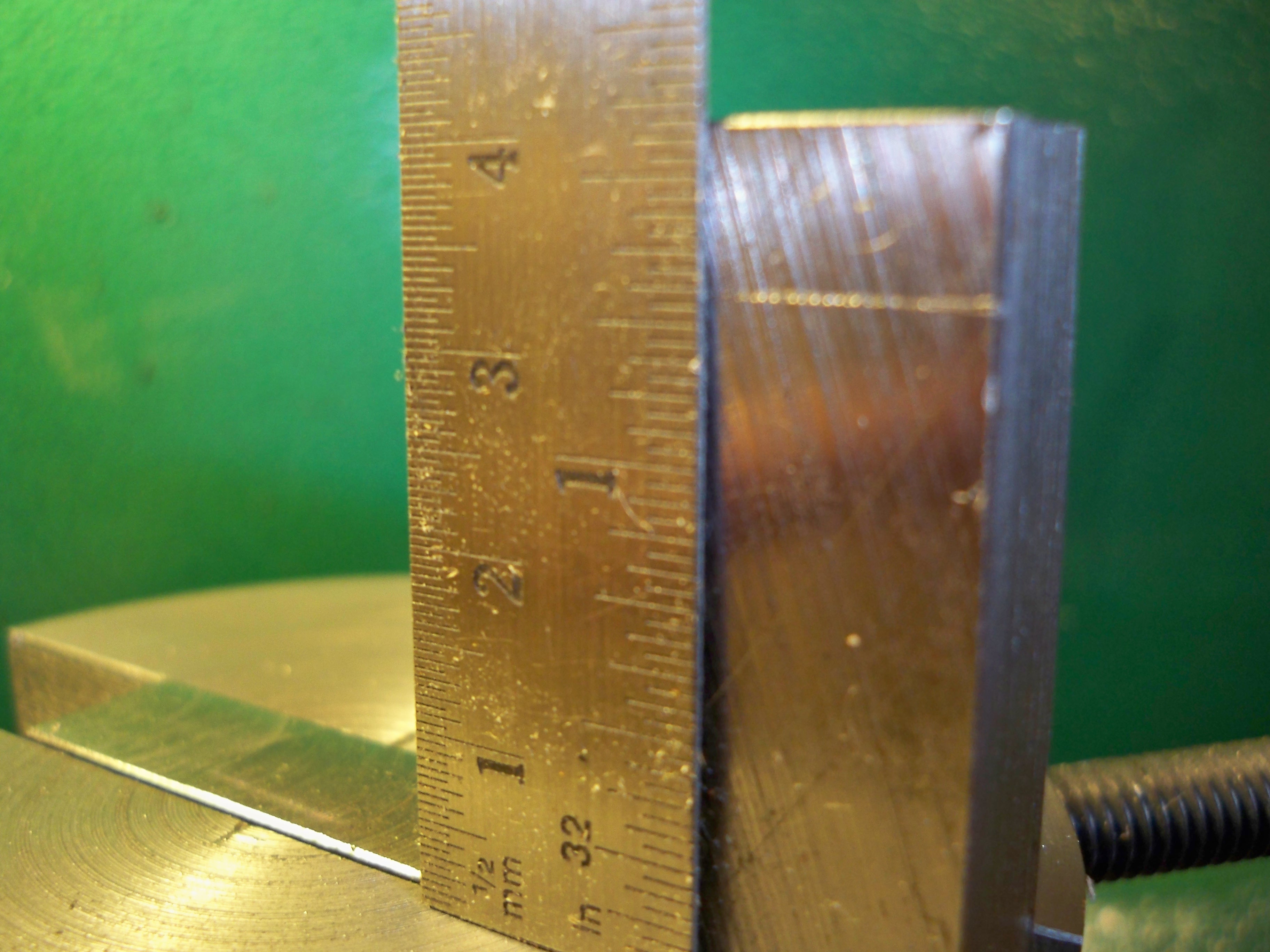
…this will be the top of the Carbide Insert. This means that this Ball Turner can turn a ball just a little greater than 2.5 inches…not too shabby!!! I won’t be able to do anything more until Sunday. Just need to mount the carbide indexes, make a real handle and of course a ball for the handle…:))
3/14/2011….I milled the tool today and I snapped off one 4-40 tap in the process. I got a little too anxious and did not use enough oil; that’s a bad combination. The tap was too small to extract so I cut that part off the tool. I will try to make another later in the week from what I learned…but it is late…12:30am on
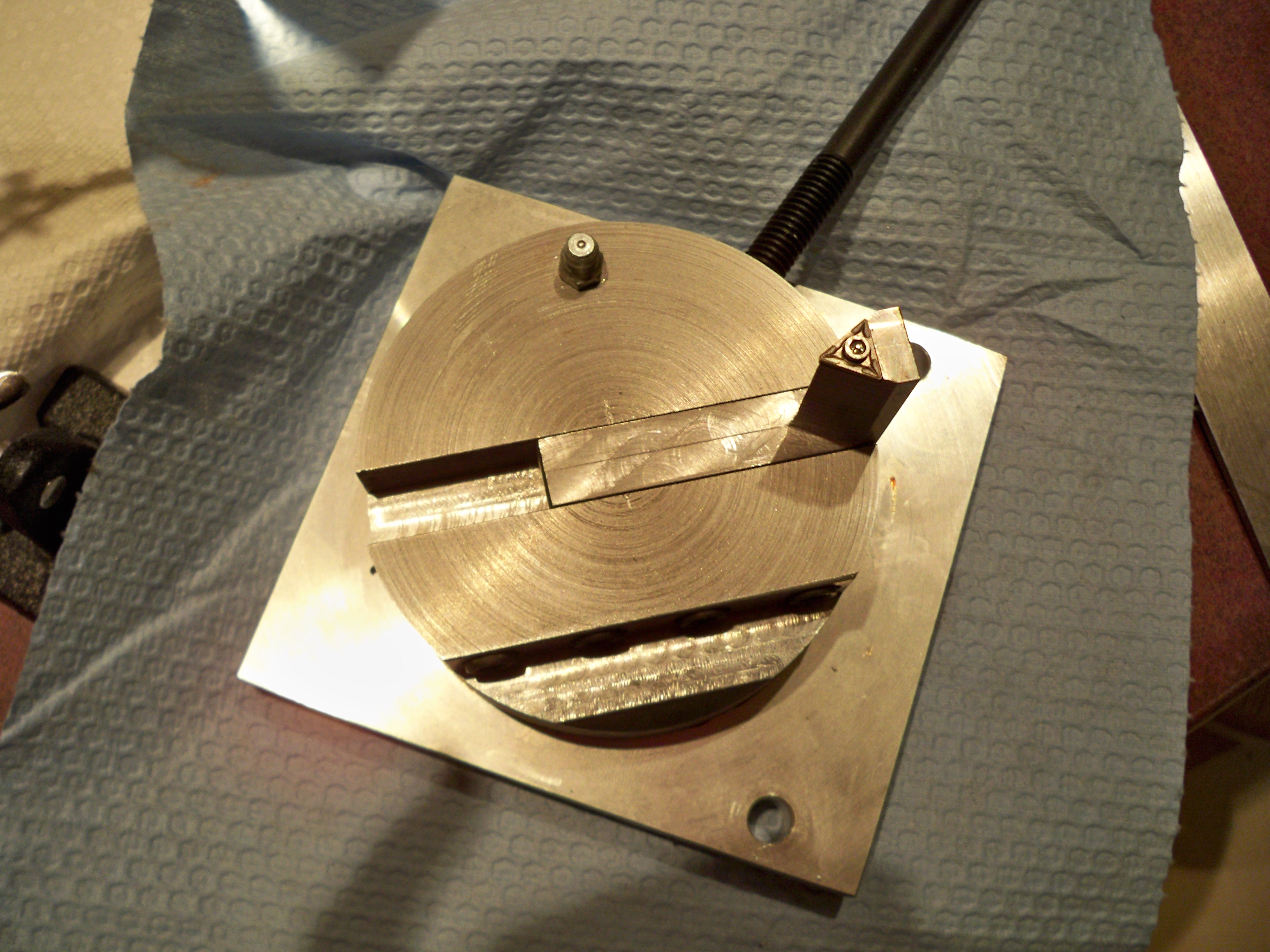
3/15/2011. This is what the ball turner looks like today without the handle….hey the finish is rough but it will work!!!
….Always trim the length of the rod close to the final diameter of the ball and make sure that is on the threaded rod tight…and move the cross slide inward in SMALL Increments!!!…why….watch….
…I stopped recording and trimmed the rod closer to the final diameter. If you are cutting aluminum or steel I would recommend FINE cuts. This next video shows a lot of progress…
…The next video, I increased the turning rate and finished the ball…then ran out of video memory…
…I will make the handle tomorrow; after I receive the 3/8-16 bottoming tap.
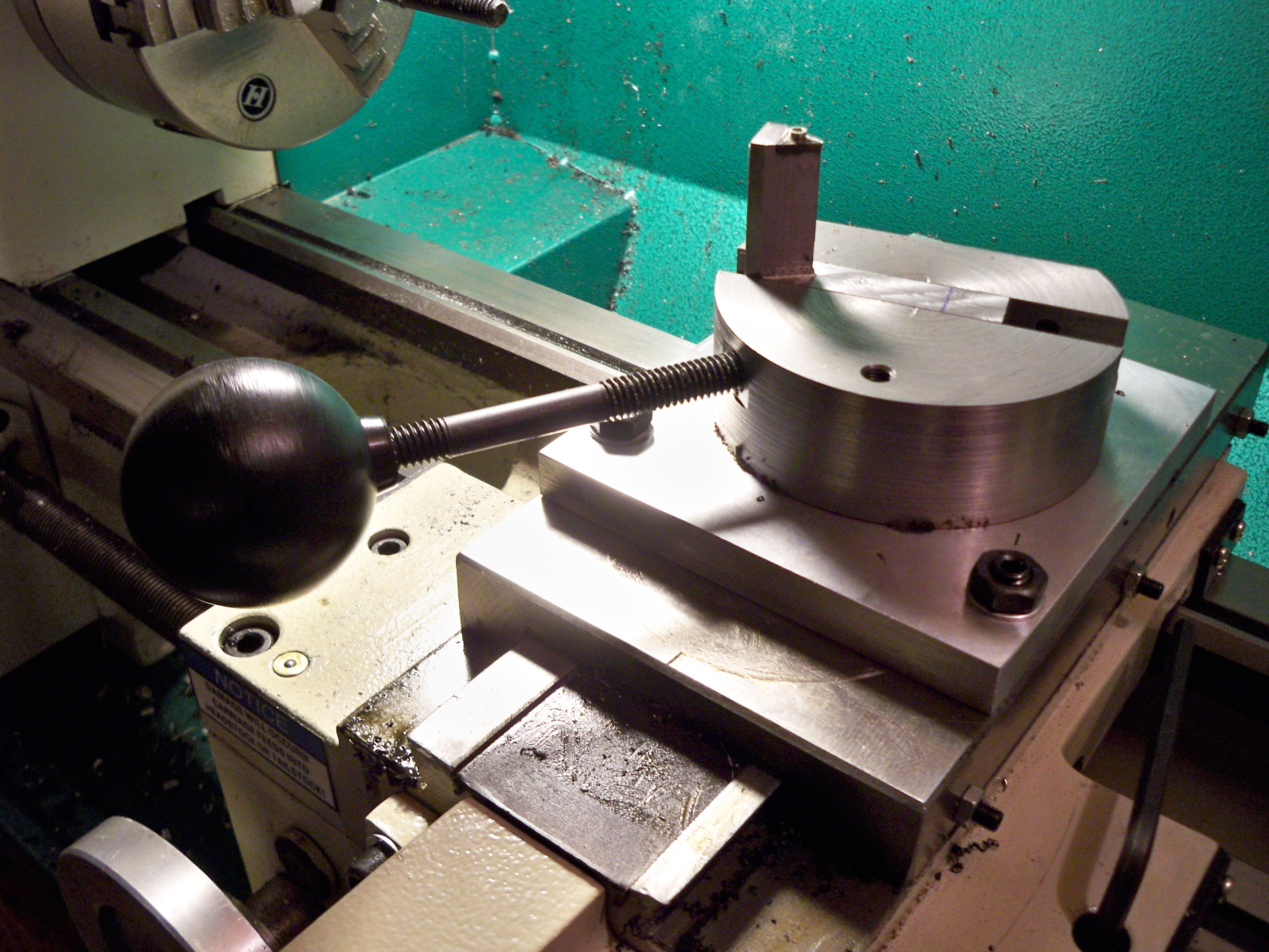
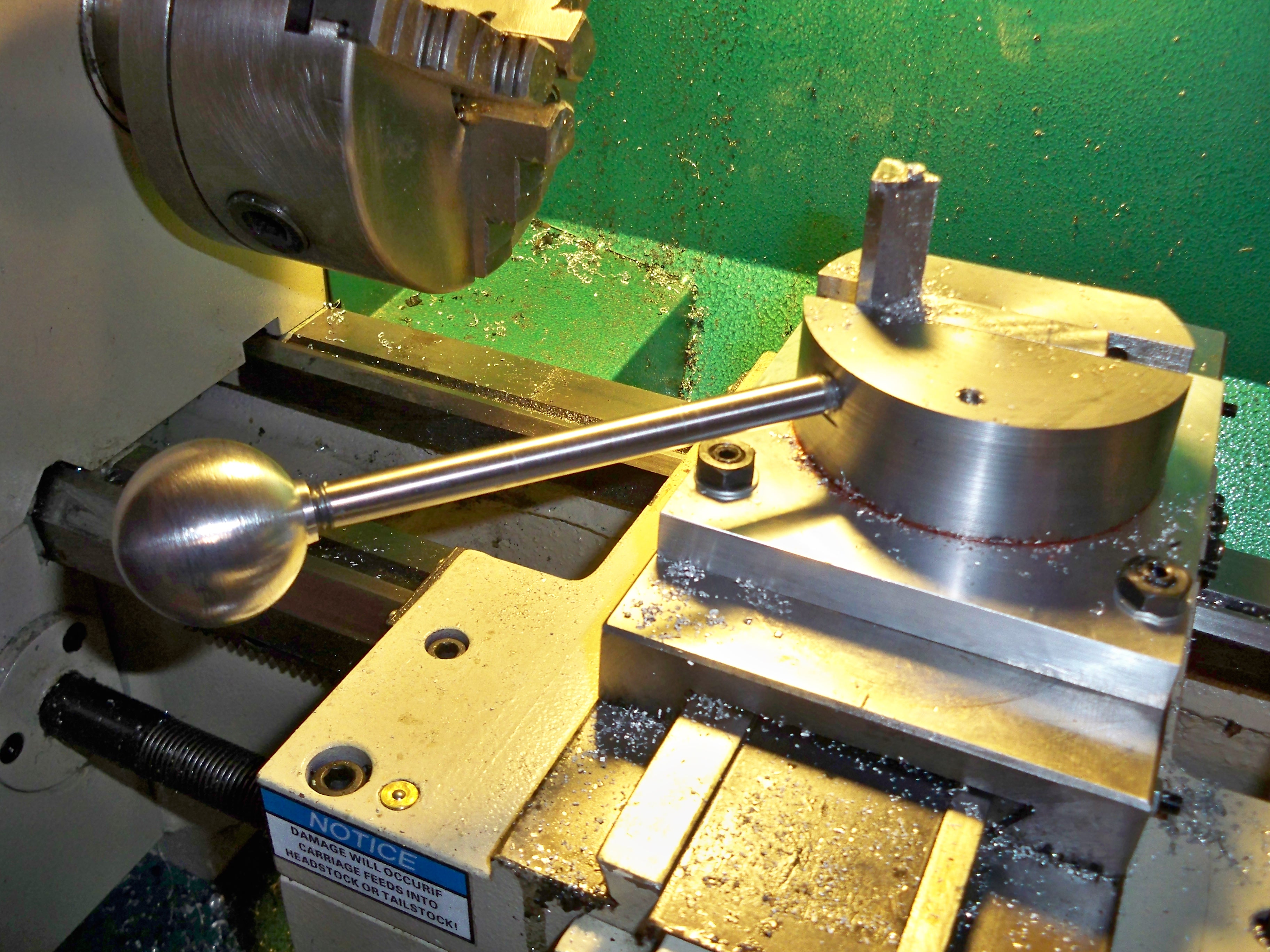
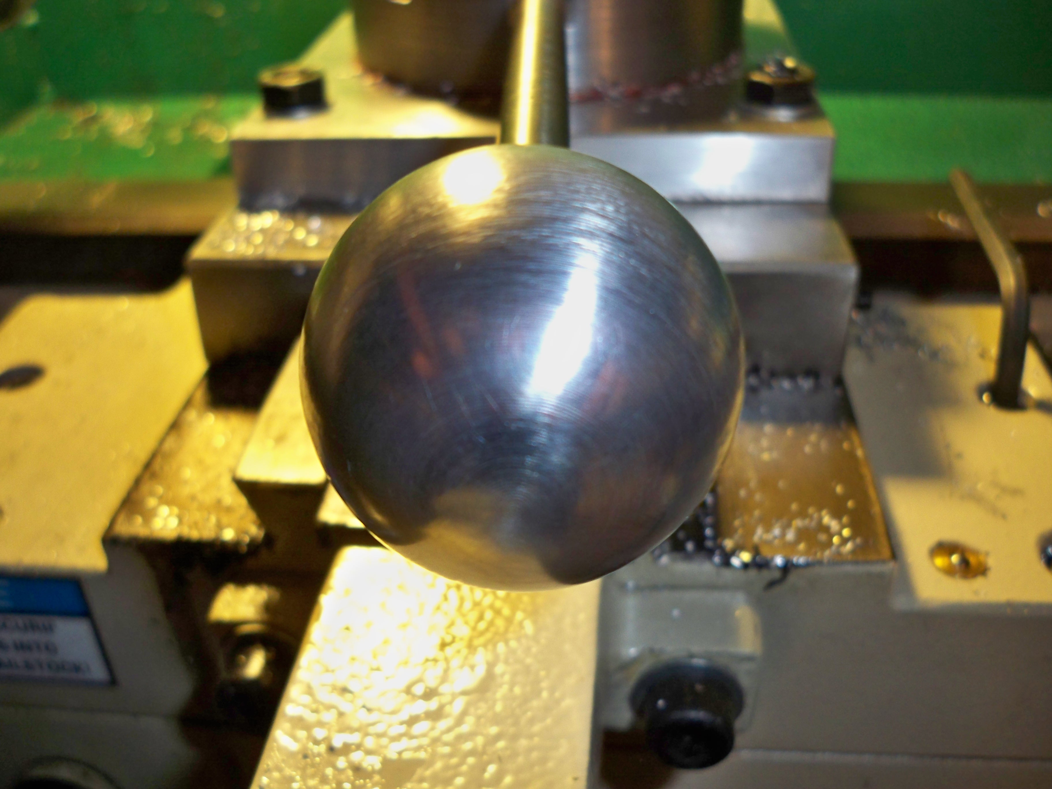
3/16/2011…I received the 3/8-16 bottoming tap, so I cut some drill rod, threaded the ends about 3/4 inch on each end and turned a 1.5 inch aluminum ball for the handle 🙂
Future modifications….
- New location for zerk fitting (Got in the way of the 2″ ball)
- A round carbide insert for a better finish.
- Concave Tool
- LH/RH Tools