Laser Head, Mirror Mounts, and Lenses
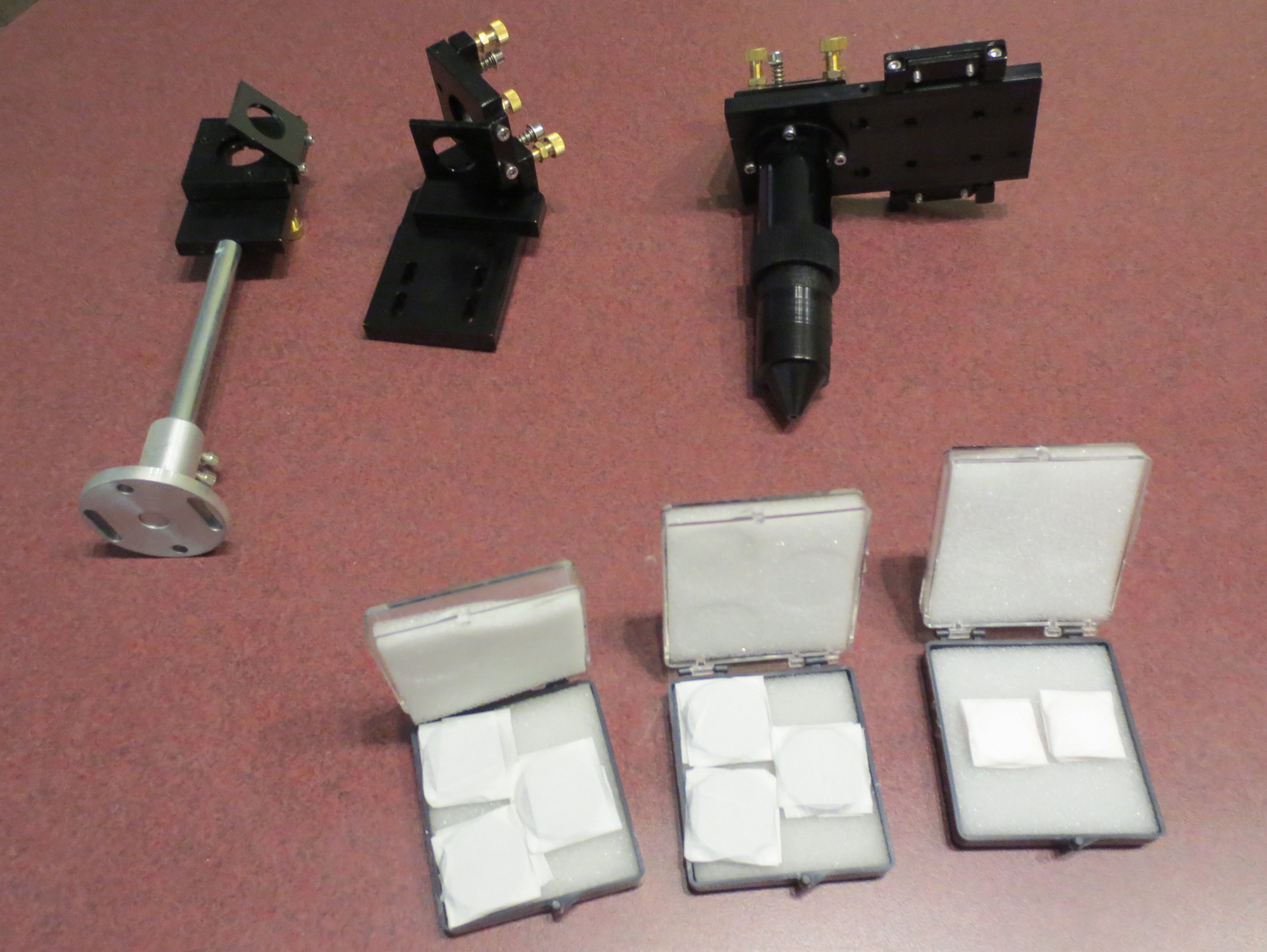
Left to Right:
- First Mirror, 25mm (Closest to Laser)
- Second Mirror, 25mm (Mounted on Y-Axis)
- Laser Head
- Third Mirror, 25mm (Mounted Along X-Axis)
- 20 mm Focus Lens (1 each)
- 3 Sets of Lens, 25mm (F63.5, F50.8, and F38.1)
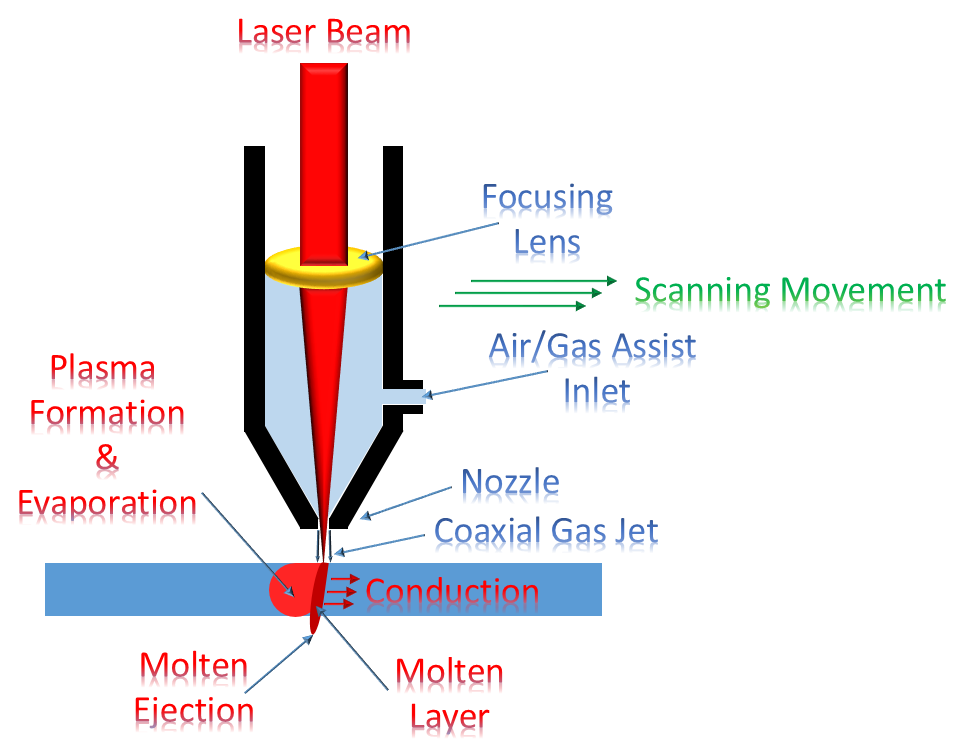
Laser Head Operation
The unfocused laser beam for an 80 Watt Laser is about the thickness of a pencil (~9mm). After bouncing off of three mirrors the unfocused laser beam passes through a Plano-convex lens to be concentrated down to a pin point. Note that this lens has one flat side and one convex surface installed on top (laser tube side) of the laser head. The focus lens is held in place by a ring nut. Compress air, 3 psi, is supplied to the laser head to keep the focus lens clean, blow smoke out of the way and to create heated gas to blow evaporated material through the cut similar to what is depicted below…
Laser Alignment
Don’t try to align your laser head this way. Though it seemed like a good idea at the time it did NOT work.
Course Machine alignment
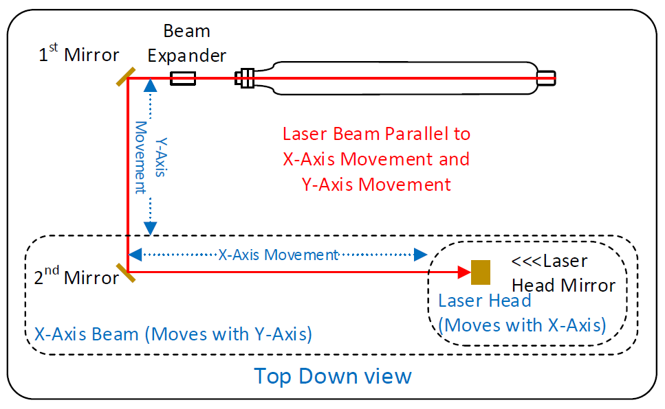
- Start with the laser
a) Align the laser parallel to the X-Axis
b) Set the height of the center line of the laser to approximately center of the laser head hole
c) Ensure that the laser is parallel to cutting table. (Easier just to make everything level) - 1st Mirror (closest to the laser tube)
a) Adjust mirror height such that the alignment hole is centered at the same height as the laser output
b) Adjust the 1st mirror alignment hole perpendicular to the laser and parallel to the Y-Axis
c) Ensure that the center line of the 1st mirror is parallel to the Y-Axis
d) Ensure that the center line of the 1st mirror and will line up with the center line of 2nd mirror. - 2nd Mirror (Moves up/down Y-Axis)
a) Ensure that the 2nd mirror height is set where the center of the mirror is centered on the laser beam and the center of the Laser Head mirror opening.
b) Ensure that the 2nd mirror is positioned along the X-Axis such that a line connecting the Y-Axis center of the 2nd mirror to the Y-Axis center of the 1st mirror is parallel to the Y-Axis movement.
c) Ensure that the 2nd mirror is positioned along the Y-Axis such that a line connecting the X-Axis center of the 2nd mirror to the X-Axis center of the Laser Head is parallel to the X-Axis movement.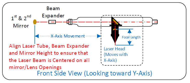
- Laser Head
a) Ensure that the Laser Head mirror opening height is set where the center of the mirror opening is centered on the laser beam and the center of the 2nd mirror.
b) Ensure that the Laser Head mirror opening is positioned along the Y-Axis such that a line connecting the X-Axis center of the 2nd mirror to the X-Axis center of the Laser Head is parallel to the X-Axis movement. - Beam Expander
a) Adjust Beam Expander height such that the input to the lens is centered at the same height as the laser output
b) Adjust the lens opening perpendicular to the laser and parallel to the Y-Axis
c) Ensure that the center line of the lens is parallel to the X-Axis and centered on the laser beam
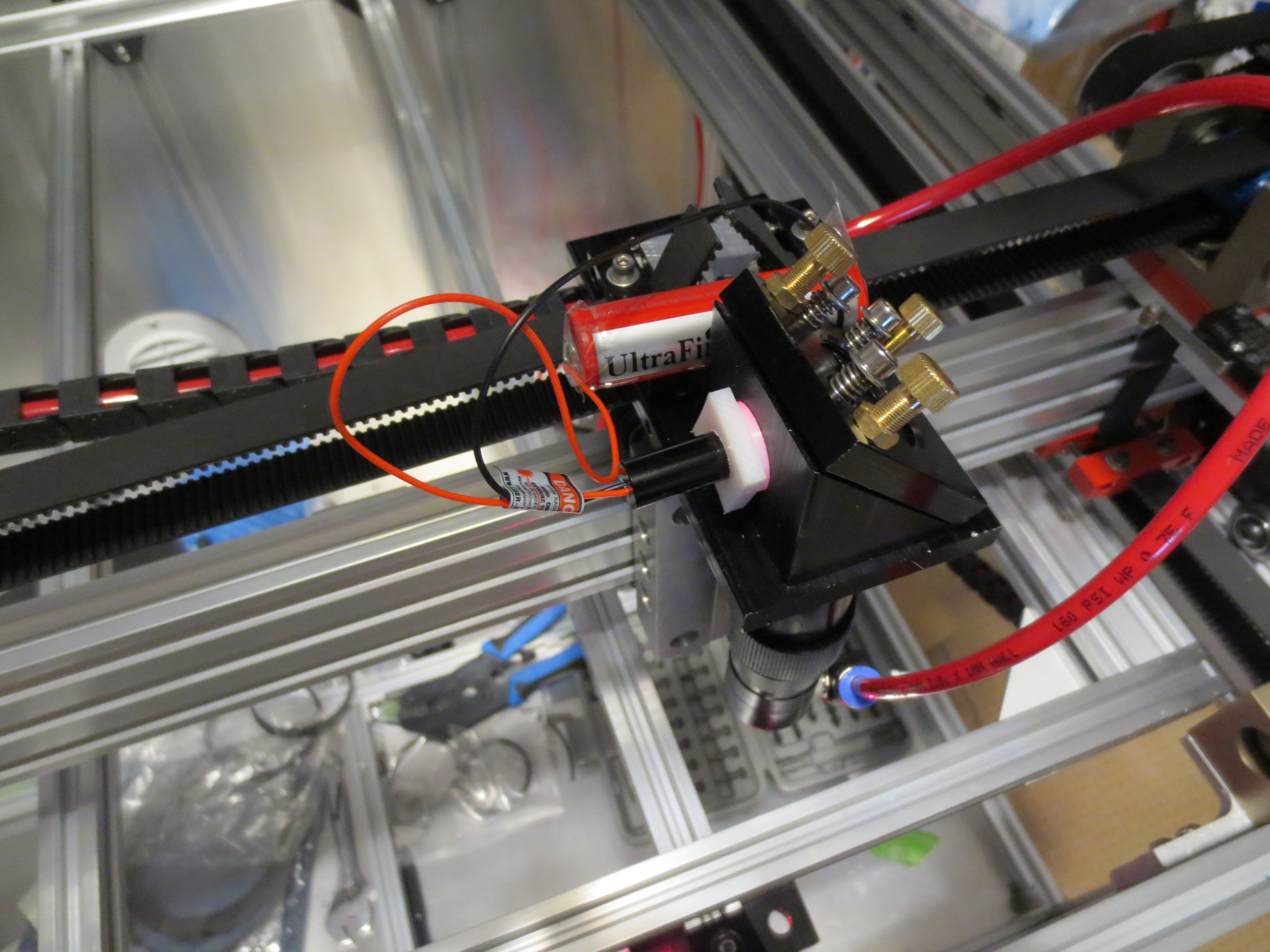
Fine Laser Beam Alignment
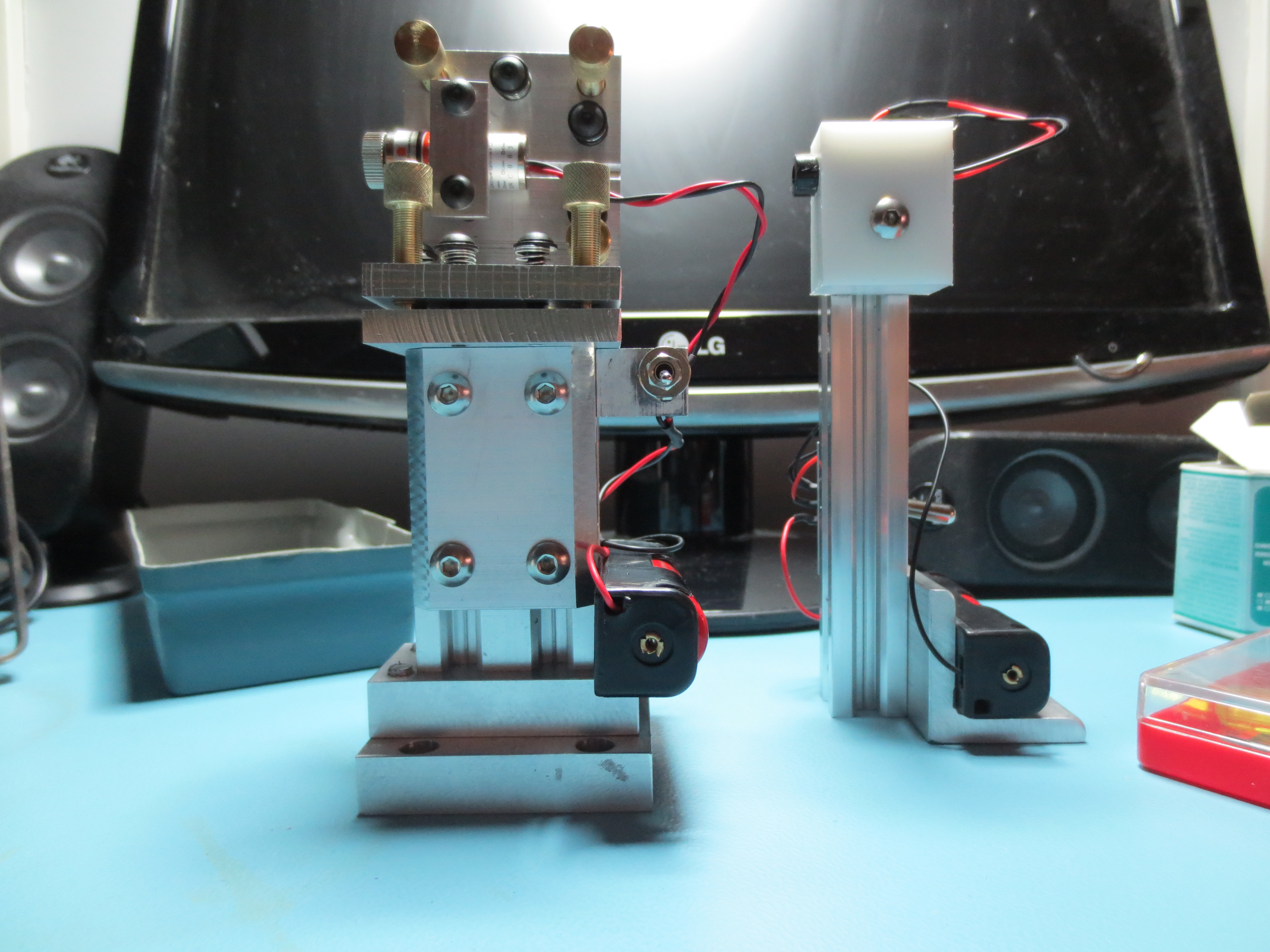
For fine laser construction I created the preceding alignment tools.
The one on the right is a single beam laser pointer and the one on the left is a “cross hair” laser pointer. I use BRC 18650 4200mAH batteries, $3 laser pointers from www.AliExpress.com. The batteries supply at 3mW these laser pointers will stay lit for a long time. Purchase a 2000+ LM flashlight with a charger and a couple of extra batteries and a 18650 battery holder and you will have inexhaustible power.
First Time Alignment
- WEAR LASER SAFETY GLASSES
- IF YOU ARE WORKING WITH THE TOP OFF, PROTECT AREAS BEHIND LASER MIRRORS JUST IN CASE YOU MISS THE MIRROR. 1/4 MASONITE WORKS.
- Cut a number of square cards out of 3×5 note cards (They don’t catch fire as easily)
- Using double sided scotch tape stick a square card across the 1st mirror alignment opening
- Note/Mark the center of the 1st mirror opening on the first card.
- Power up the chiller, Laser Controller, have a wet sponge ready.
- Briefly press the <TEST> fire button on the laser controller long enough to burn spot on the card. (use wet sponge to stop card smoldering)
- Determine the deltas up/down, left/right (difference between the center of the 1st mirror alignment opening and the burn spot.
- Move 1st mirror alignment opening up/down and left/right by the delta amount. Repeat steps 4. through 8. until the 1st mirror is aligned.
- Once the 1st mirror is aligned. Remove the square card.
- Move the 2nd Mirror along the Y-Axis to a point farthest away from the 1st Mirror.
- Using double sided scotch tape stick a FULL 3×5 card across the 2nd mirror alignment opening
- Note/Mark the center of the 2nd mirror opening on the first card.
- Power up the chiller, Laser Controller, have a wet sponge ready.
- Briefly press the <TEST> fire button on the laser controller long enough to burn spot on the card. (use wet sponge to stop card smoldering)
- Note where burn spot is and adjust the 1st mirror to align the spot to the center of the 2nd mirror alignment opening. Note: If you don’t hit the card check the masonite. Leave card in place on 2nd mirror.
- Using double sided scotch tape, stick the square card across the 1st mirror opening.
- Note/Mark the center of the 1st mirror opening on the square card.
- Briefly press the <TEST> fire button on the laser controller long enough to burn a “SMALL” hole in the square card on the 1st mirror. (use wet sponge to stop card smoldering)
- Power down Co2 laser tube. Do Not move the Y-Axis.
- Using the a red laser dot alignment jig (see above right). Turn red laser dot on and fire it through the first hole on the 1st mirror and hit the center of the burn spot on the 2nd mirror 3×5 card.
- Move the Y-Axis close to the 1st mirror noting the position of the red laser dot. Hopefully the dot is in the same spot. If not, split the difference between dot position in 21. and 22. and adjust the first mirror to that point. (If the dot doesn’t move the laser is close to parallel alignment in the Y-Axis)
- Move the 2nd Mirror along the Y-Axis to a point farthest away from the 1st Mirror. Did the red laser dot move? If so, split the difference between dot position in 22. and 23. and adjust the first mirror to that point. (If the dot doesn’t move the laser is close to parallel alignment in the Y-Axis)
- Repeat 22. and 23. until the red laser dot does not move.
- If the red laser dot is a least within the 2nd mirror alignment opening proceed.
- If the red laser dot is too far left/right, move the 1st mirror farther/or closer to the laser tube. Moving the 1st mirror farther from the laser tube moves the red laser dot right and moving the 1st mirror closer to the laser tube moves the laser dot left.
- If the red laser dot is too high/low, consider whether or not the height of the center of the 2nd mirror is equal to the center height of the 3rd mirror.
- If the center height of the 2nd and 3rd mirrors are not equal, make them equal. CAUTION REMOVE RED LASER POINTER!!! Repeat steps 4. through 25.
- If the center height of the 2nd and 3rd mirrors are equal, measure the difference between the red laser dot and center height of the 2nd mirror. Raise/lower the laser and the first mirror by difference in height. CAUTION REMOVE RED LASER POINTER!!! Repeat steps 4. through 25.
- CAUTION REMOVE RED LASER POINTER!!! Remove all targets.
- Using double sided scotch tape, stick the 3X5 card across the 3rd mirror opening.
- Move the 3rd mirror along the X-Axis to the point farthest away from the 2nd mirror.
- Note/Mark the center of the 3rd mirror opening on the third card.
- Briefly press the <TEST> fire button on the laser controller long enough to burn spot on the 3×5 card. (use wet sponge to stop card smoldering)
- Repeat step 30. while making small adjustments in the 2nd mirror until the burn spot is moved to the center of the 3rd mirror. Then burn a small hole in a clean target at the center of the 3rd mirror.
- Using double sided scotch tape, stick the square card across the 2nd mirror opening.
- Note/Mark the center of the 2nd mirror opening on the square card.
- Briefly press the <TEST> fire button on the laser controller long enough to burn small hole in the square card. (use wet sponge to stop card smoldering)
- Using double sided scotch tape, stick the square card across the 1st mirror opening.
- Note/Mark the center of the 1st mirror opening on the square card.
- Briefly press the <TEST> fire button on the laser controller long enough to burn small hole in the square card. (use wet sponge to stop card smoldering)
- Disable the Co2 Laser.
- Using the red laser dot alignment jig, adjust the red dot laser to shine through the 1st, 2nd, and 3rd cards.
- Move the 3rd mirror along the X-Axis close to the 2nd mirror. Is the red laser dot still shining through the hole in the target on the 3rd mirror?
- Split the difference between the center hole of the target on the third mirror and where the red laser spot is located when the 3rd mirror is closest to the 2nd mirror; mark the split difference point.
- Adjust the 2nd mirror to the location of the split difference. Move the 3rd mirror to a point along the X-Axis farthest away from the second mirror.
- If the dot moves mark the split difference point again and adjust the 2nd mirror accordingly. Move the 3rd mirror to a point close to the 2nd mirror, it should not move.
- If the red dot no longer moves when moving 3rd mirror along the X-Axis, is the red laser dot centered?
- If the dot is not centered up and down, assess whether you can shim the laser head or move the laser tube, 1st, and 2nd mirrors up and down. CAUTION REMOVE RED LASER POINTER!!! Repeat all alignment steps.
- If the dot is not centered left or right, shift the 2nd mirror forward or aft to center the beam on the laser head. CAUTION REMOVE RED LASER POINTER!!! Repeat all alignment steps.
- If the dot is centered on the 3rd mirror, proceed.
- Place a 3×5 card under the laser head at the focal point.
- Adjust the 3rd mirror until you see the red laser dot with a centered corona.
- CAUTION REMOVE RED LASER POINTER!!! REMOVE ALL TARGETS.
- Briefly press the <TEST> Co2 laser button.
- You should have a pin hold through the 3×5 card. If not, repeat all steps.
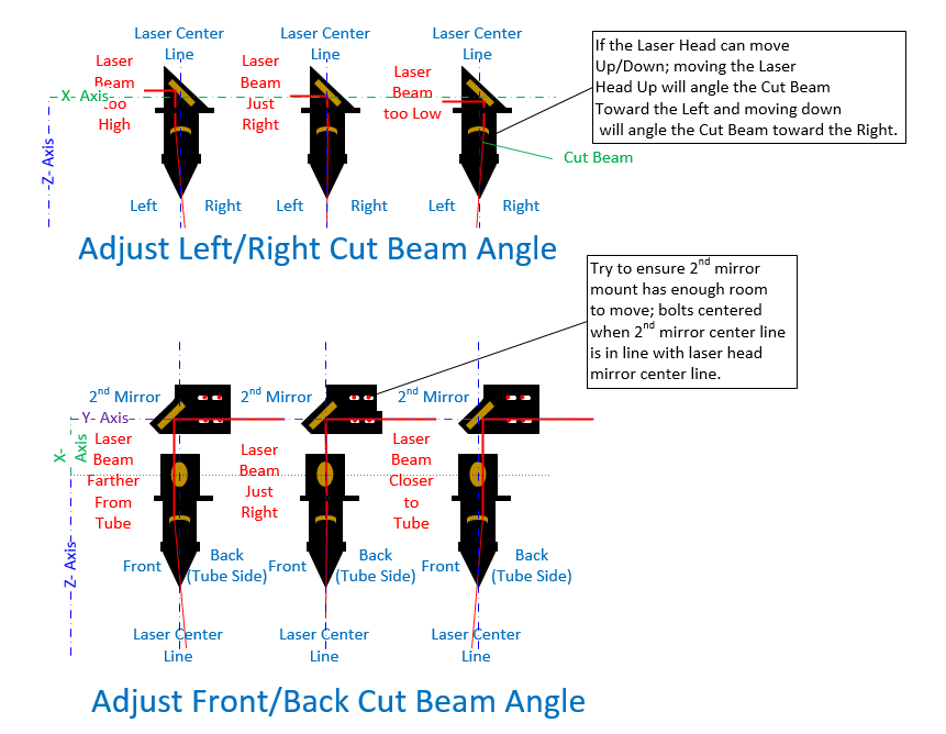
Cut Beam Adjustments
The focused laser beam (what I am calling the cut beam) out of the Laser Head may have an slant/angle to it depending on how close to the center of the lens the beam was aligned. This Cut Beam Angle may not be corrected using only the laser head thumb screws (only very fine adjustments dependant upon the size of your laser head nozzle). Adjusting all three Thumbscrews in/out will move the Cut Beam end Left/Right. You may have to move the laser beam height up/down by moving the Laser Tube/Laser Head to move that Cut Beam Left/Right or you may have to move the 2nd mirror along the Y-Axis to move the end of the Cut Beam forward or backward toward the tube.
To test for errors in the cut beam angle cut a 1 inch circle out of thick stock (e.g. 3/4 wood). If the cut beam angles are correct you will have a 3/4 inch cylinder. If not, you will have what looks like a slant stack of quarters. If you look close, there is still some error there. Note some of the angle is caused by the burning through of such thick stock (ei. More burn at the top then the bottom when cutting speed is slow).