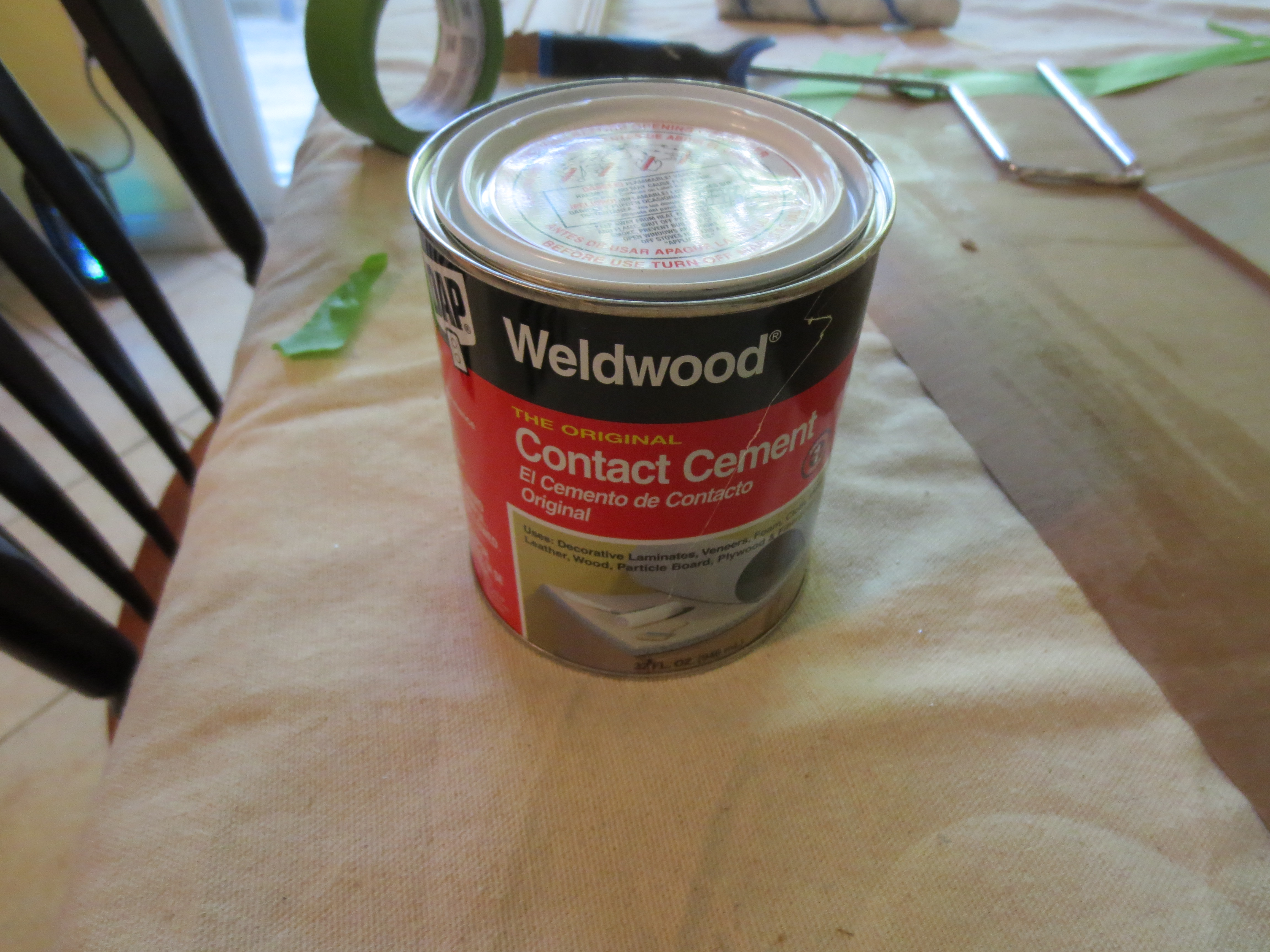
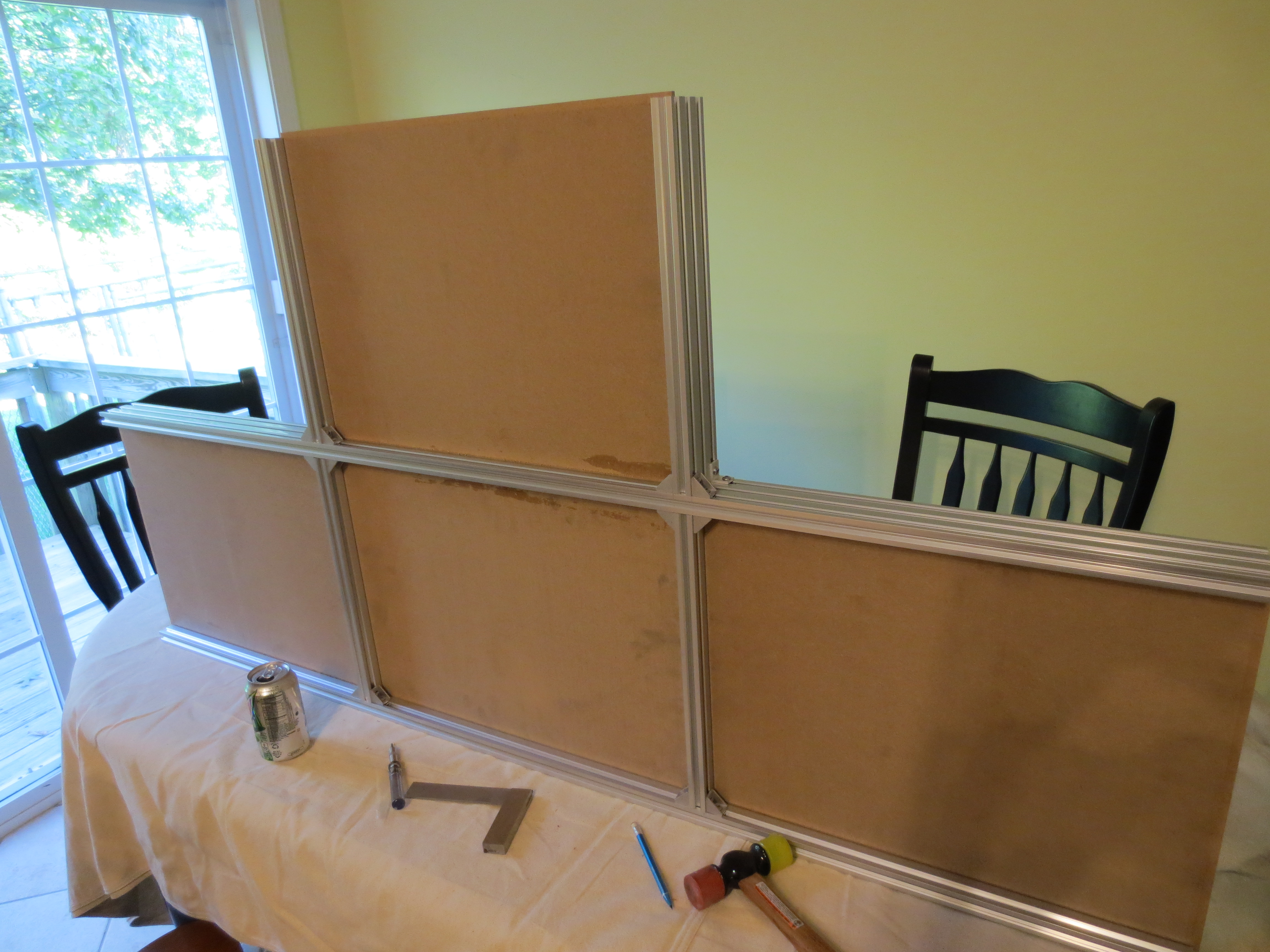
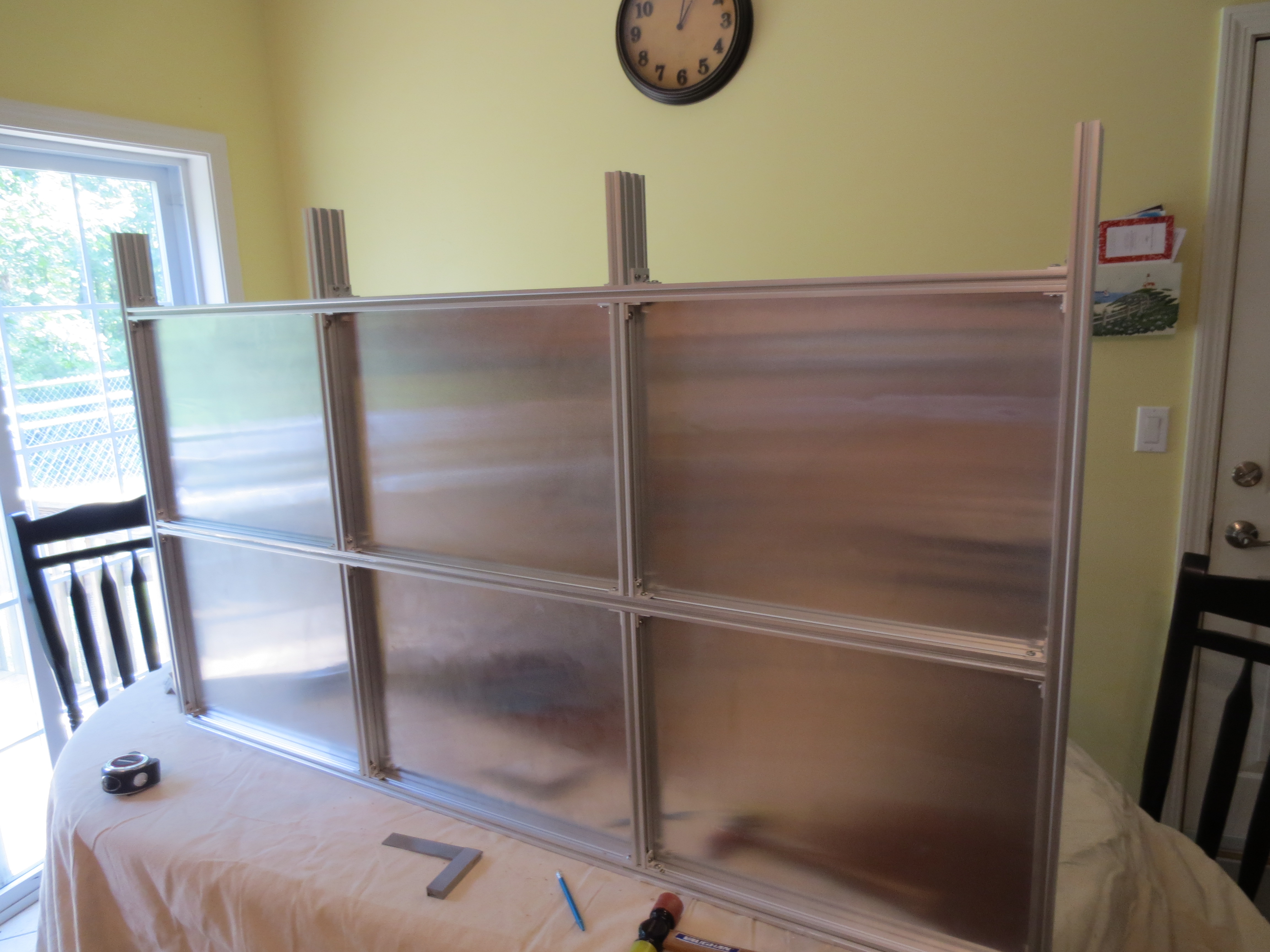
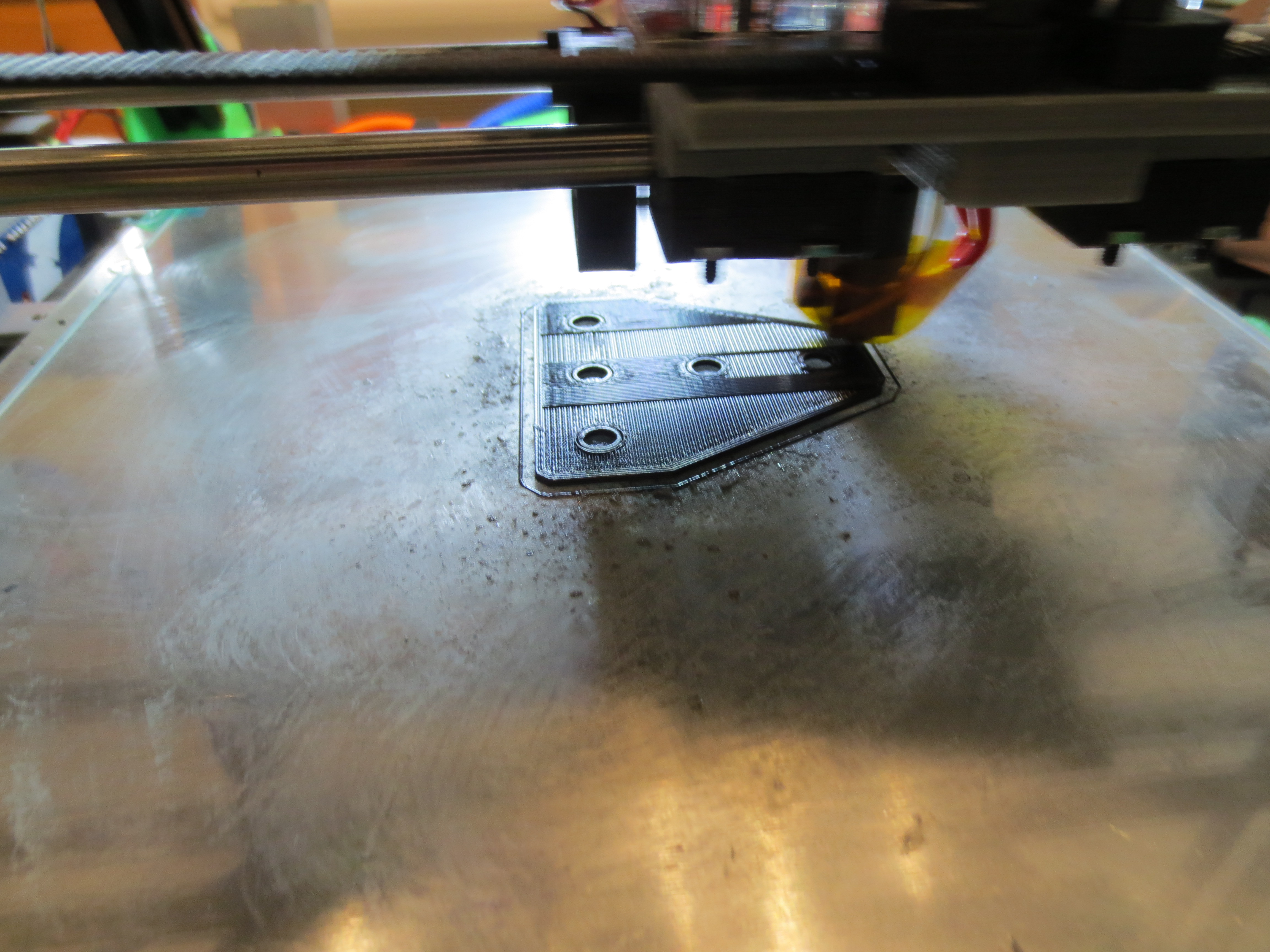
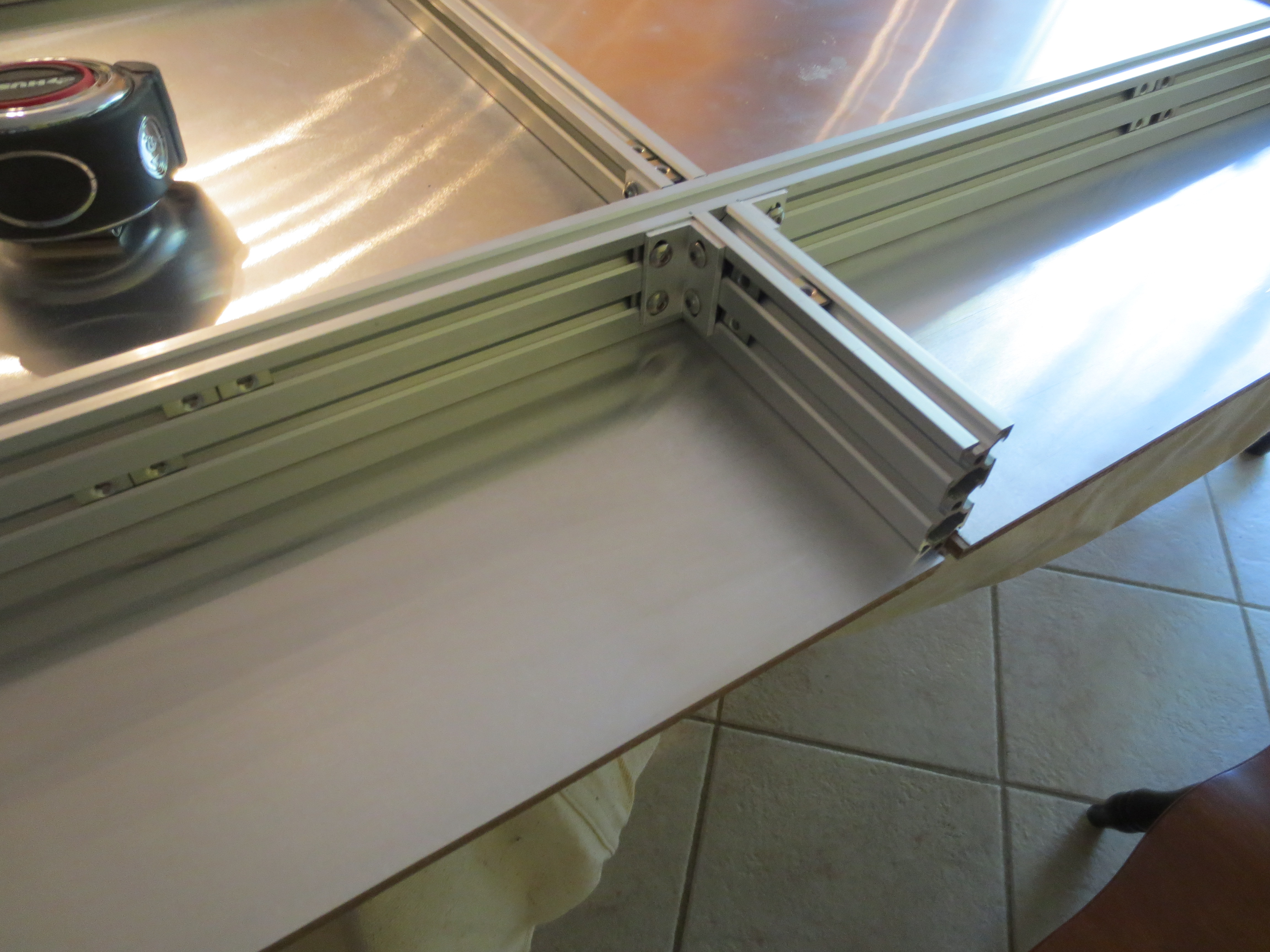
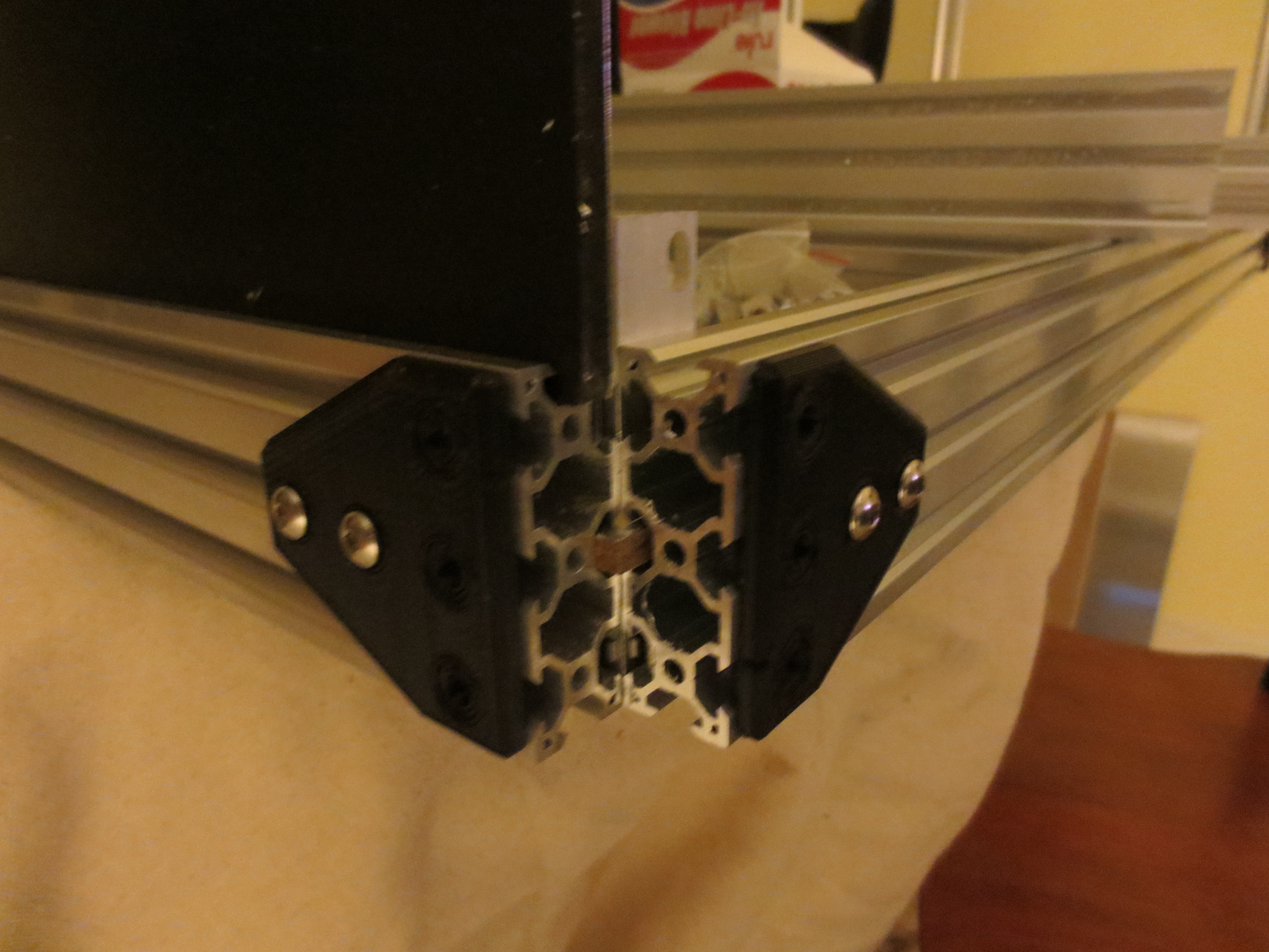
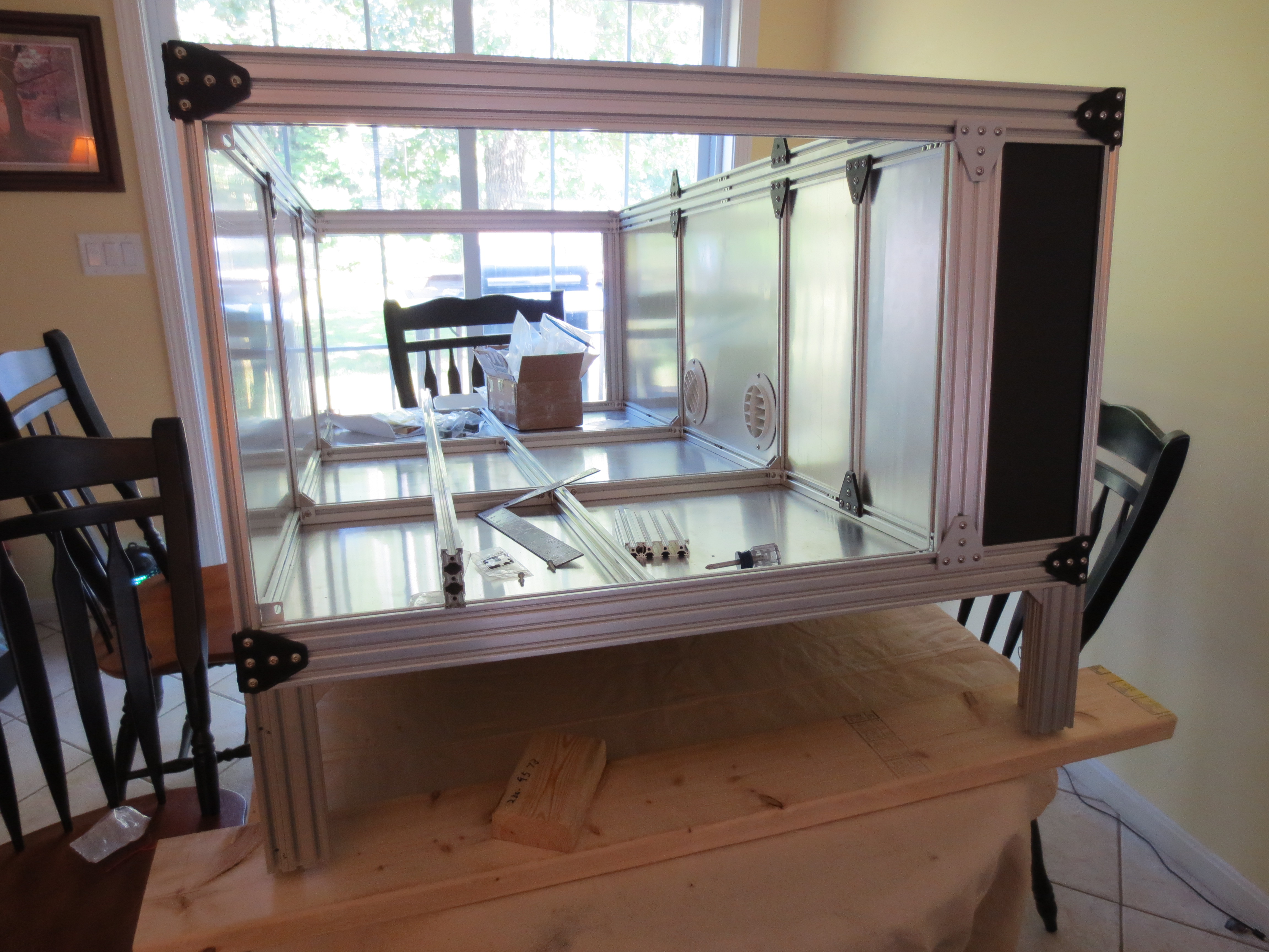
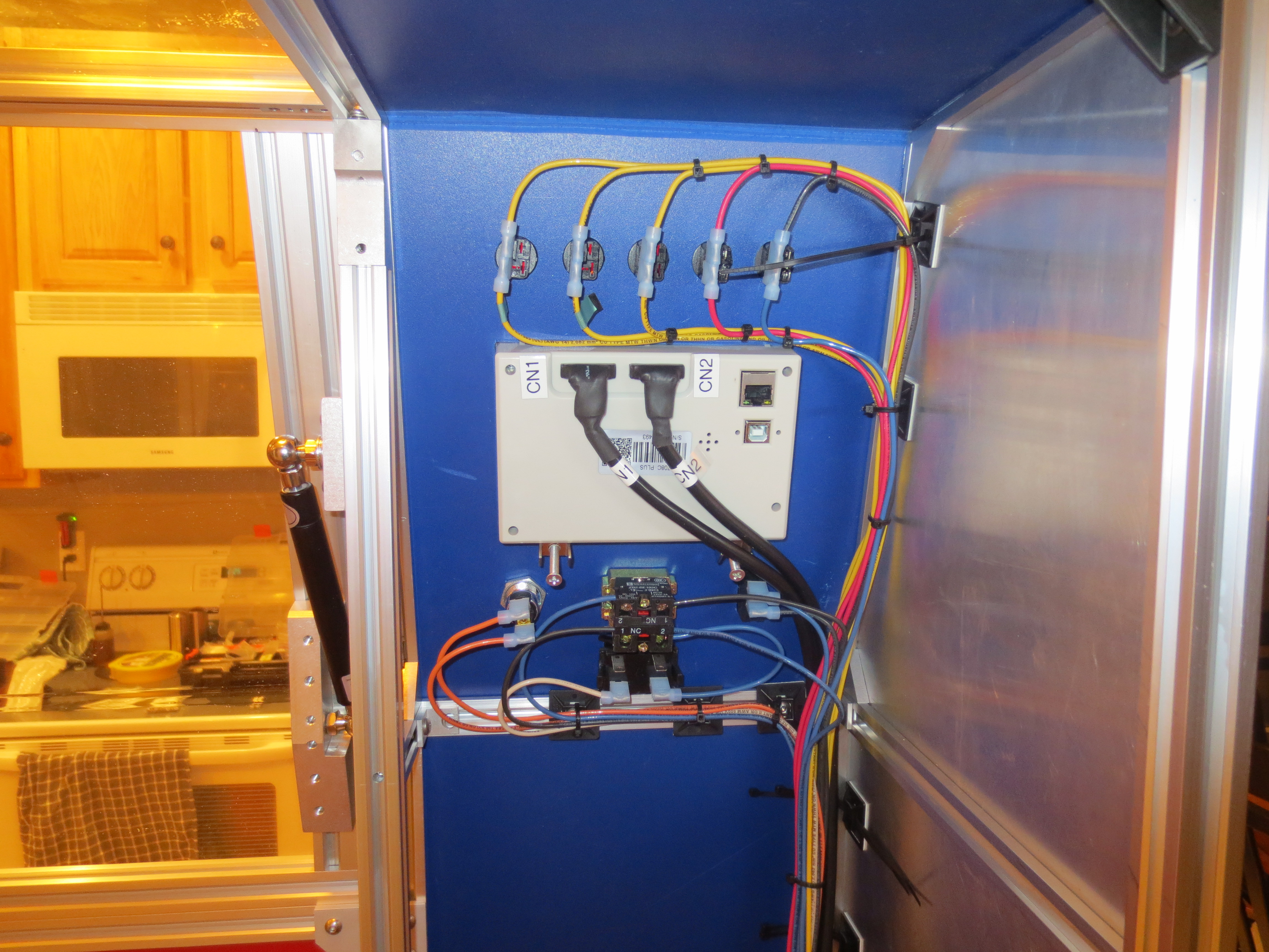
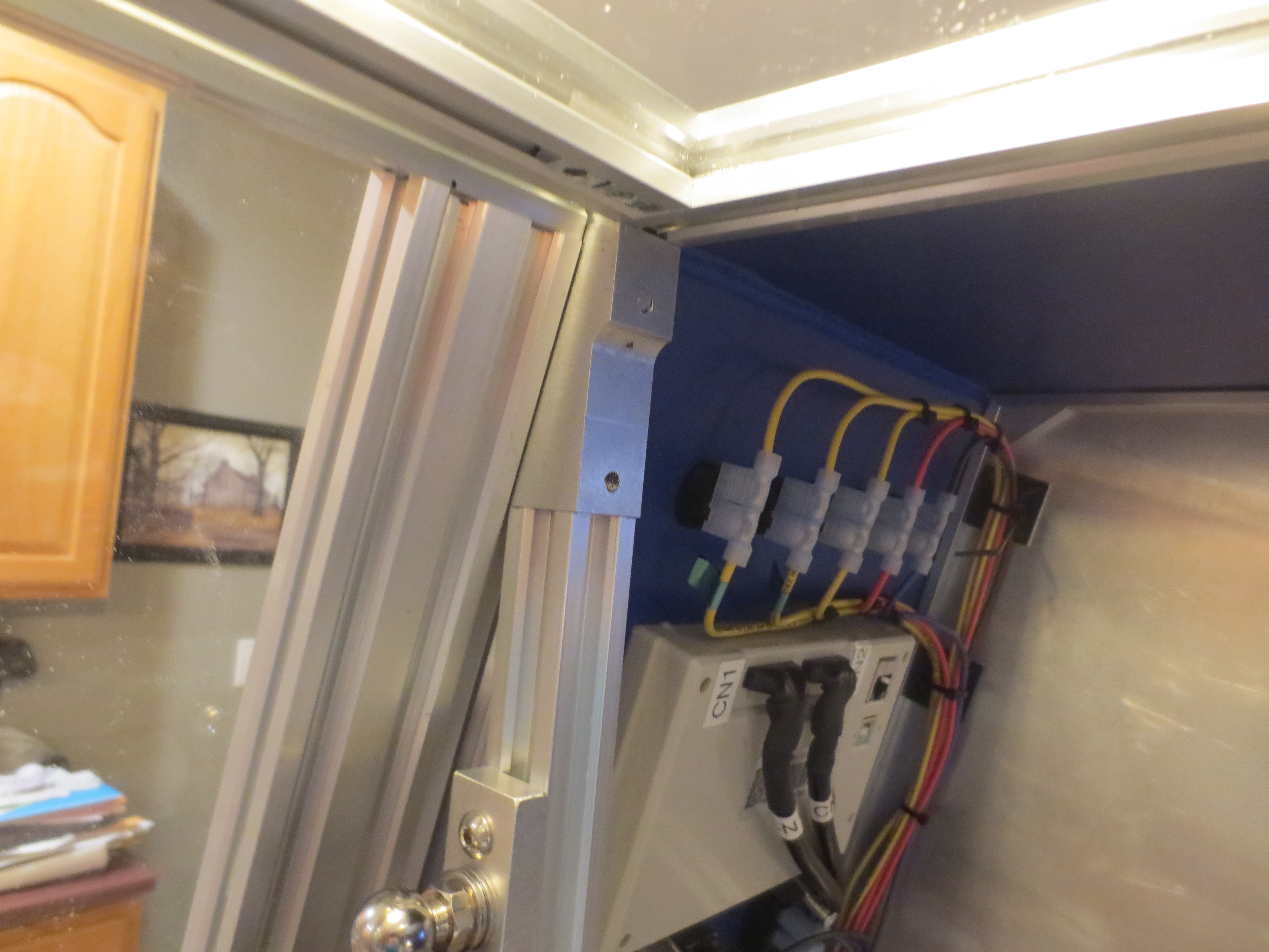
This story begins in the kitchen. I fabricated the laser cabinet using vslot and hardware from www.openbuildspartstore.com. I used expanded PVC and 1/4″ MDF panels laminated on one side with aluminum flashing and rubber cement from Home Depot. The black plates I printed on the 3D printer to save a few dollars.
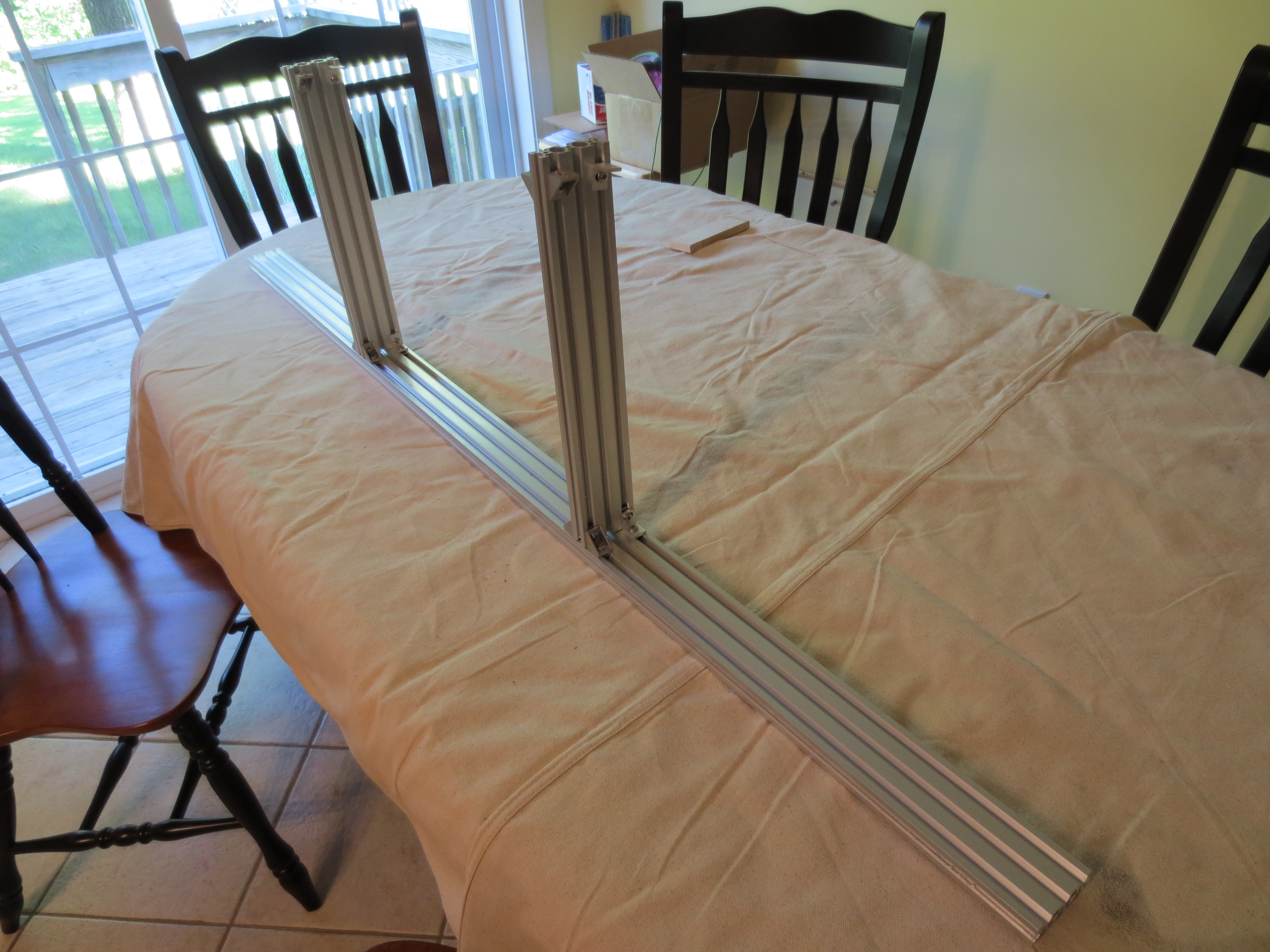
The acrylic window for the top cover of the Laser Cutter was fabricated using a home made bender…
Quick Homemade Plastic bender
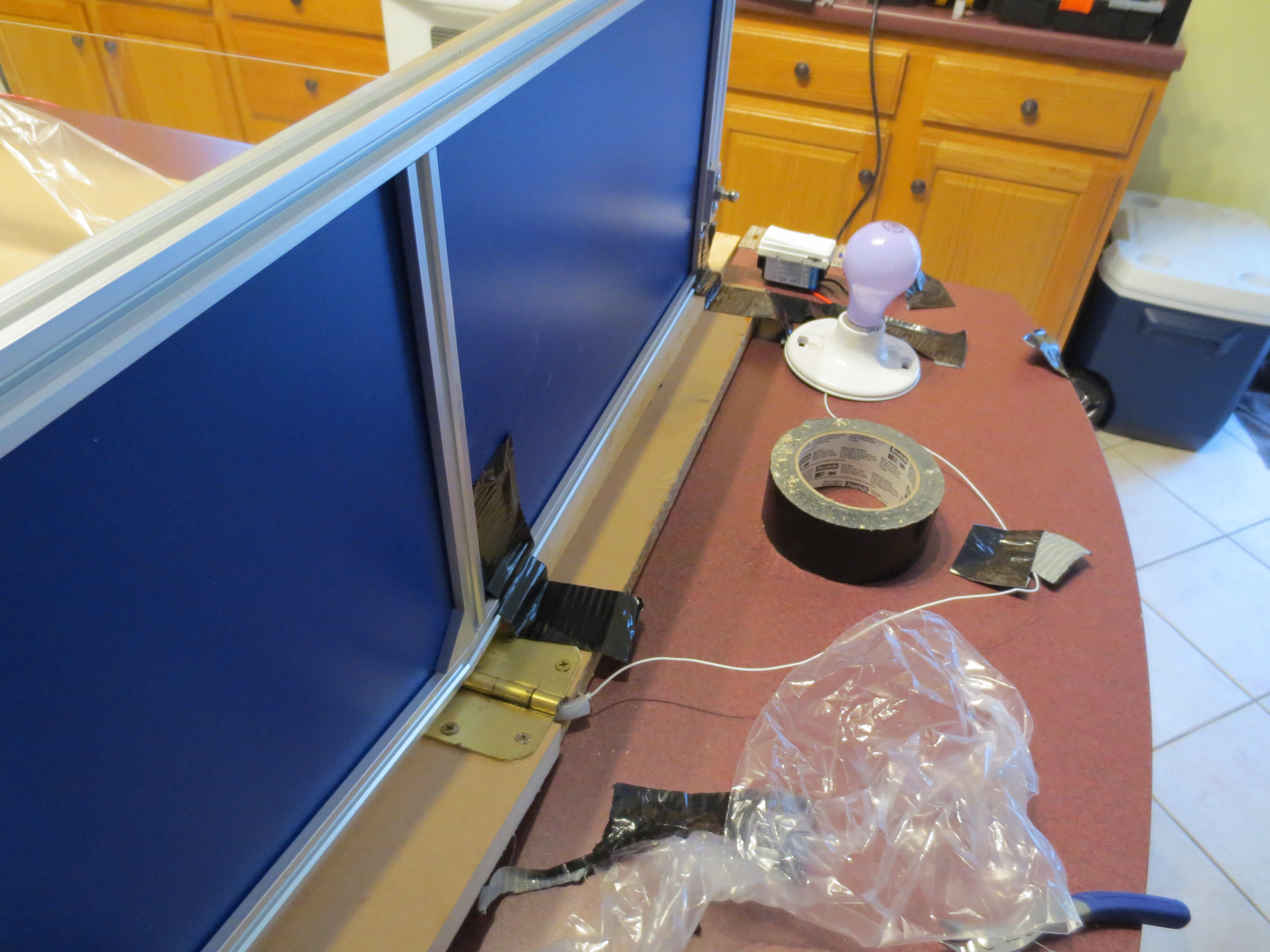
40+ Inches of 21 AWG Nichrome wire; 1/2 inch U-channel; two hinges; MDF board; a spring; Surgical tubing, 16 AWG THHN; Teflon wire White); terminal lugs; an IR thermometer and a dimmer switch set on it’s lowest setting (Warning: Do NOT try this if you do not understand electronics.). The lightbulb was only used for terminal connections.
The following picture only shows one piece of wood screwed to the MDF as clamping board; note that I actually I used two boards, one on each side of the bender (you can still see the screw hole). The second board had a 45 degree bevel to allow for a tighter bend.
I heated the Acrylic Plastikote (Purchased at Lowes) to 230 degrees and turned off the dimmer switch. Most plastic manufactures have specification sheets on their websites; that’s where I found the temperature information. I bent the plastic and allowed it to cool for a minute and removed the second clamp before lowering the hinge side. Note the spring. Nichrome wire expands when heated so you need a spring to take up the slack. Also note that the Nichrome wire is suspended above the aluminum U-channel; I used surgical tubing as an insulator. Maybe someday I will make a real plastic bender. I spent $3.00 for springs and $16.20 for 20 feet of 21 AWG Nichrome wire; delivered from www.skycraftsurplus.com. The rest was scrap from other projects. I duct taped the top to the bender to ensure I got the angles right. At $26 dollars a sheet, I did not want to make a mistake.
Putting the cover together…
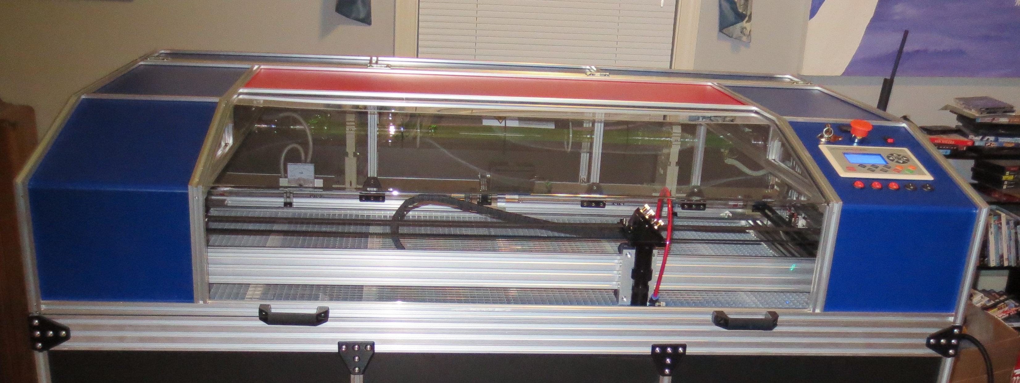
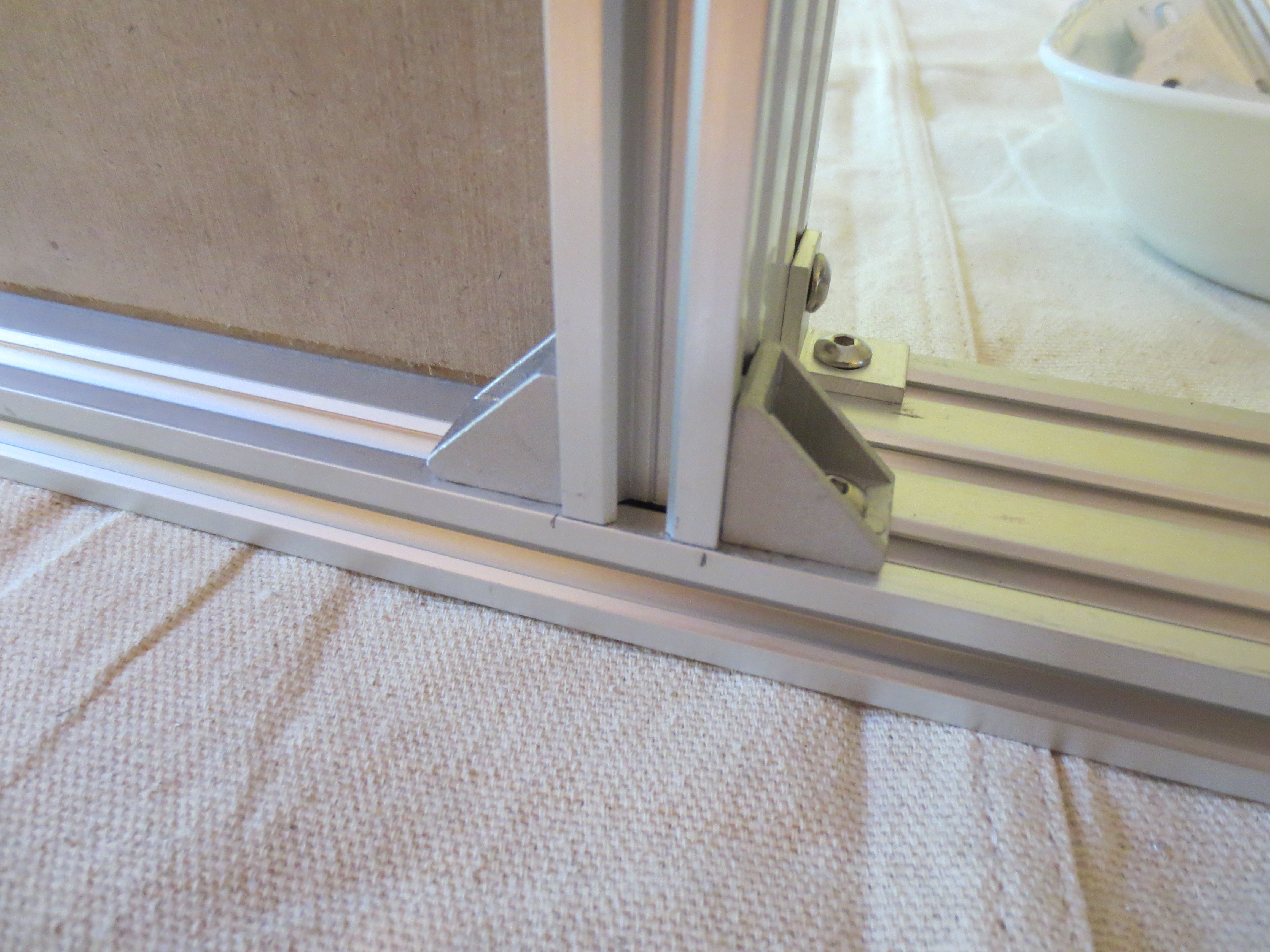
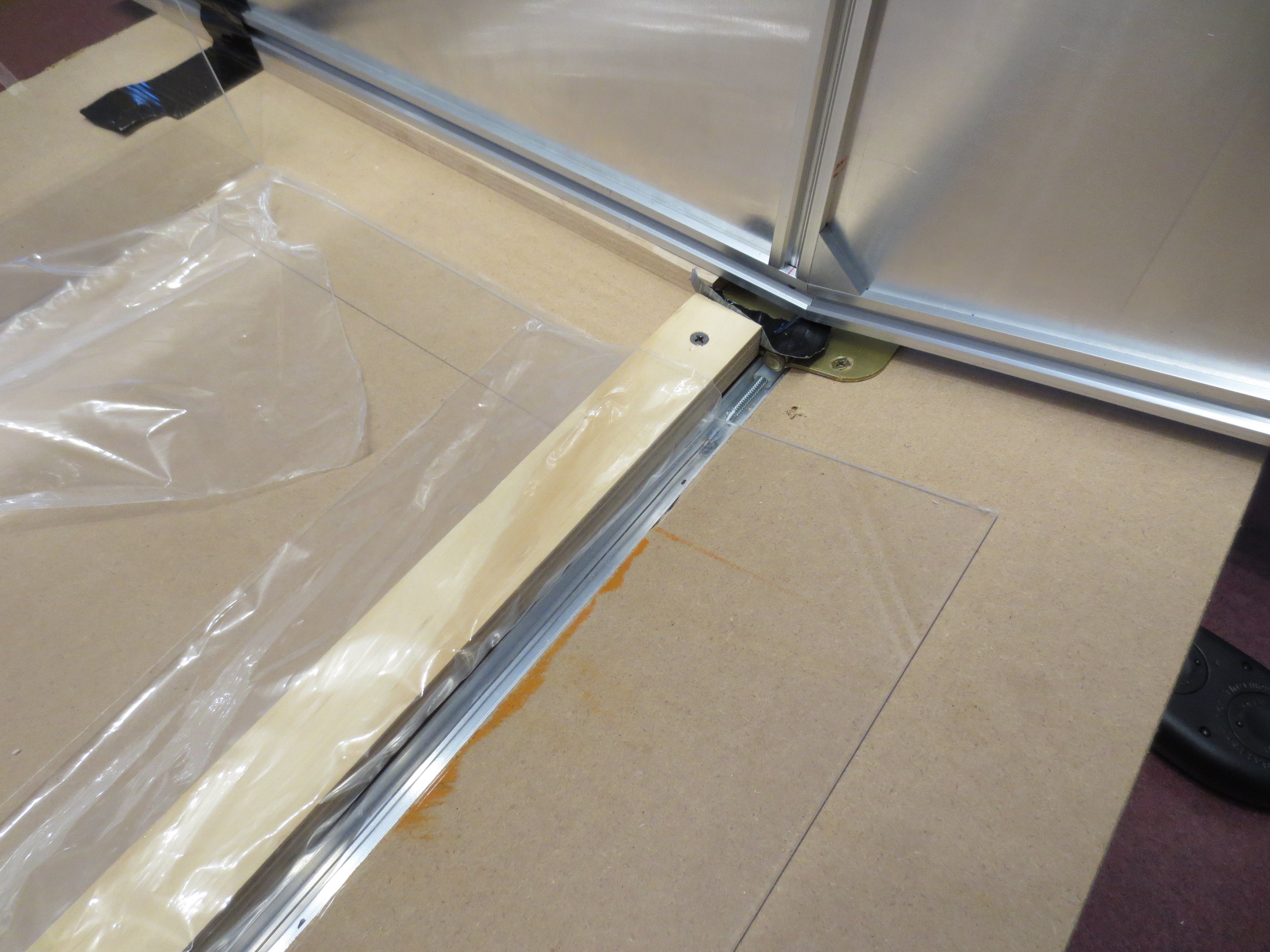
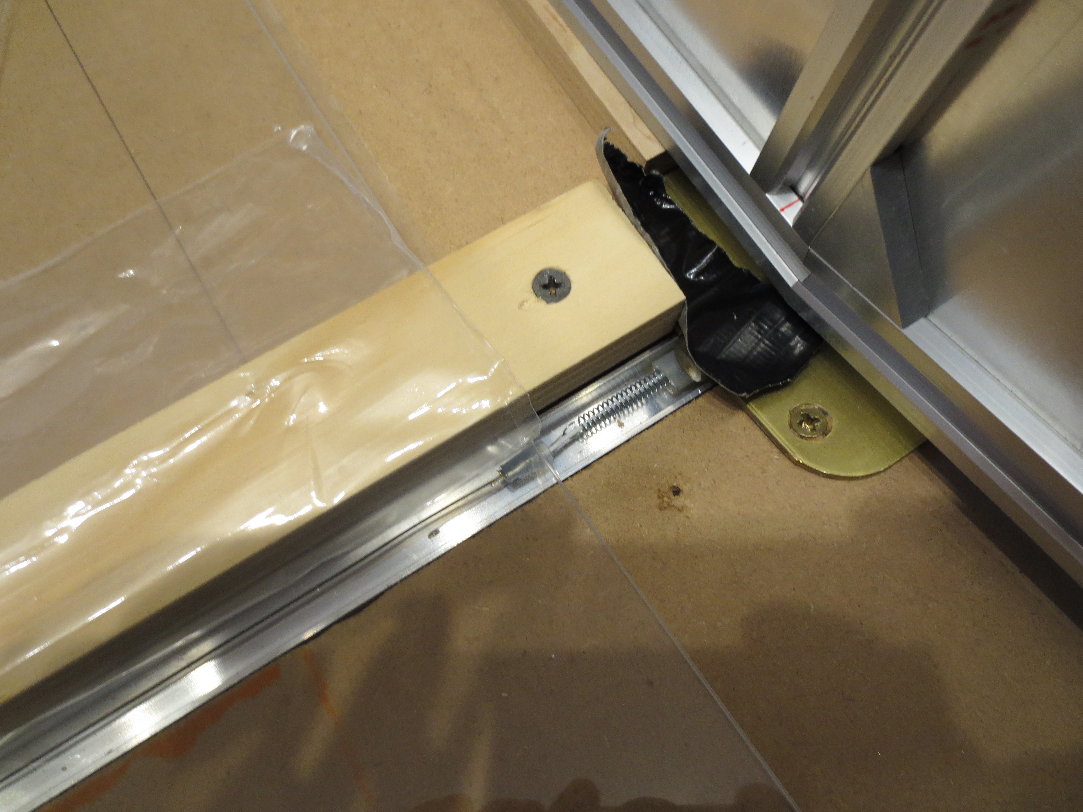
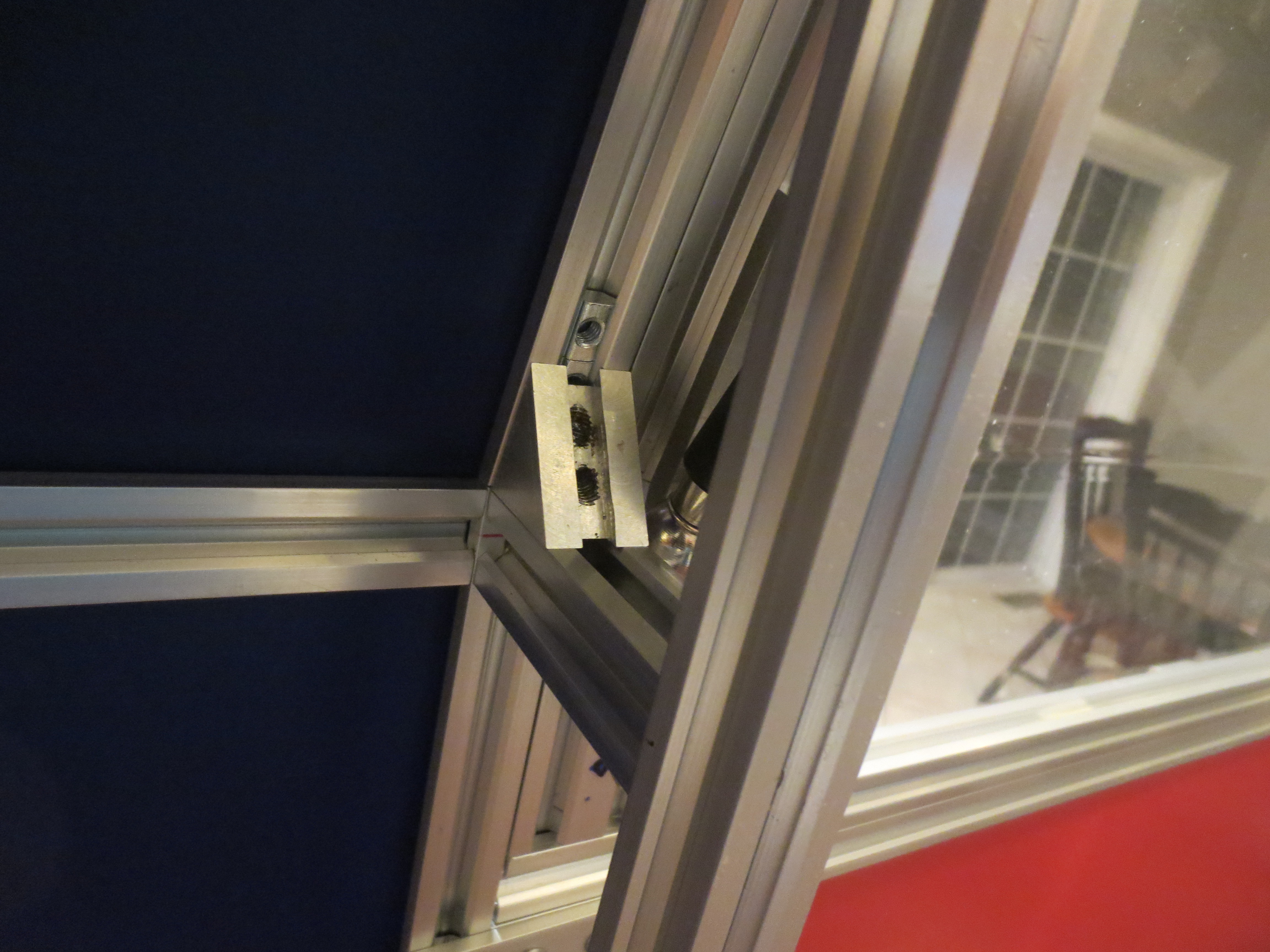
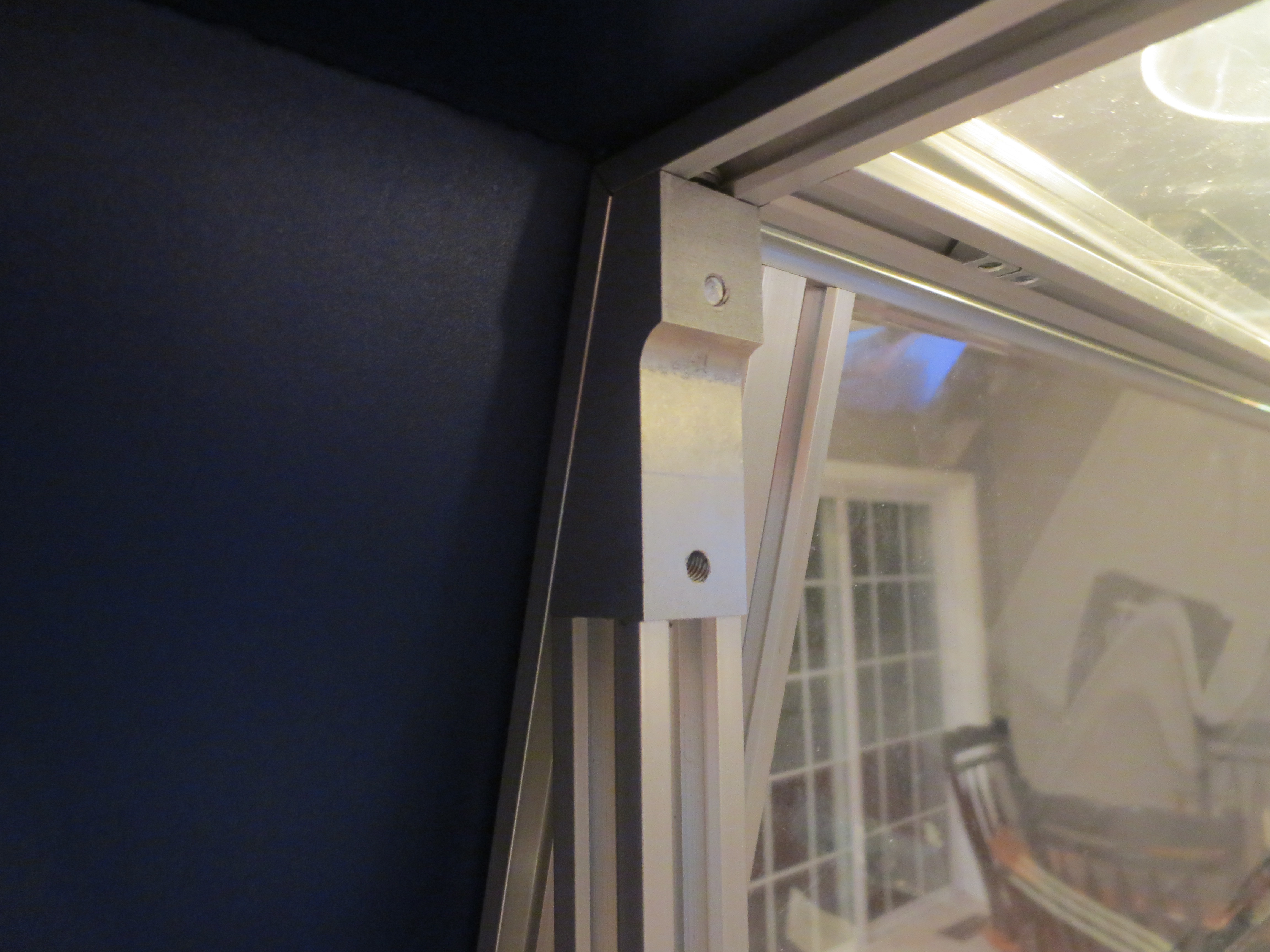
Though opening the whole top was workable, I thought it might be better to just be able to open up the center part were most of the action happens. Of course this required a number of unique parts fabricated out of aluminum and a couple of gas shocks purchase on Ebay.
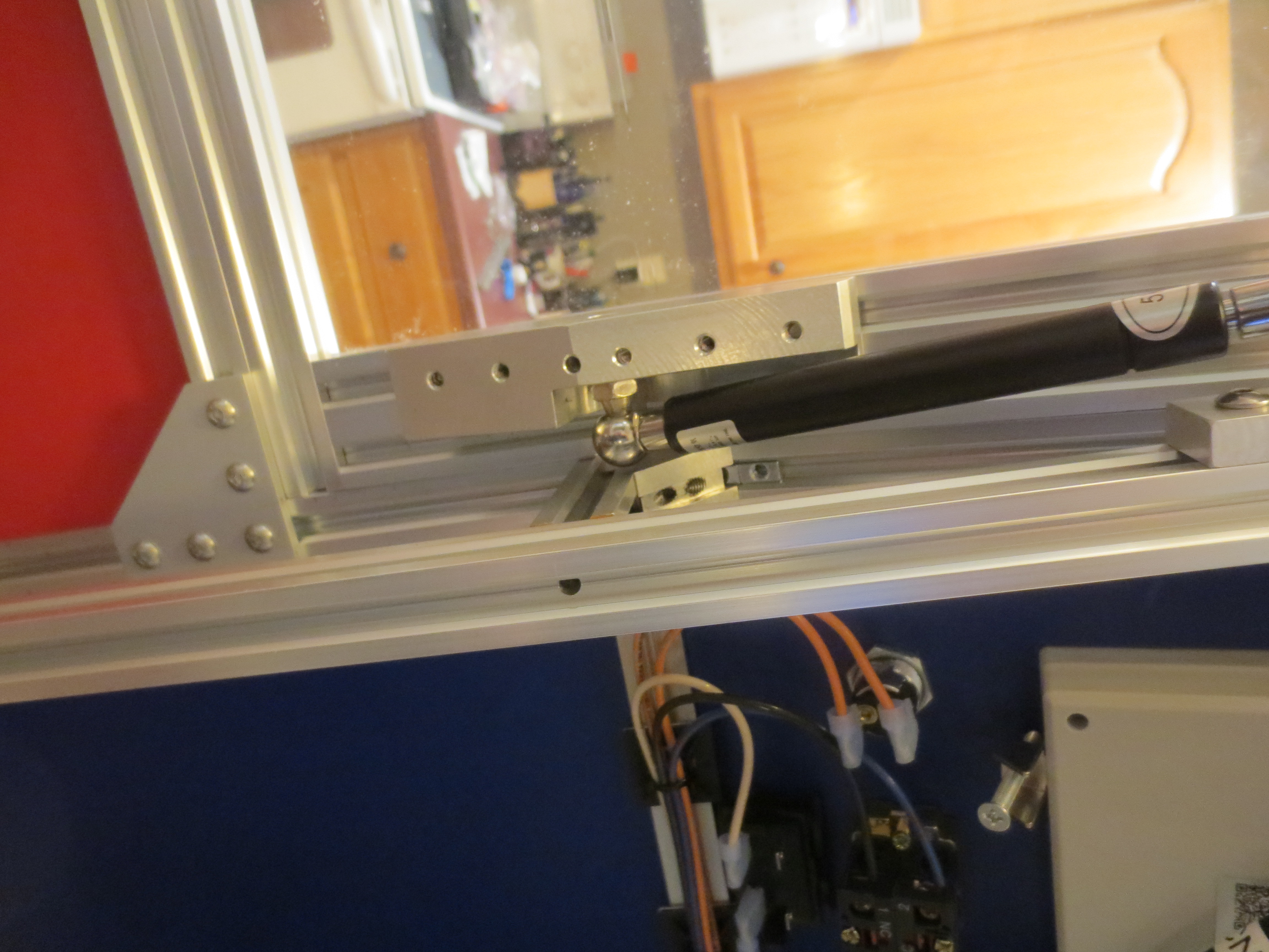
The new door in action…
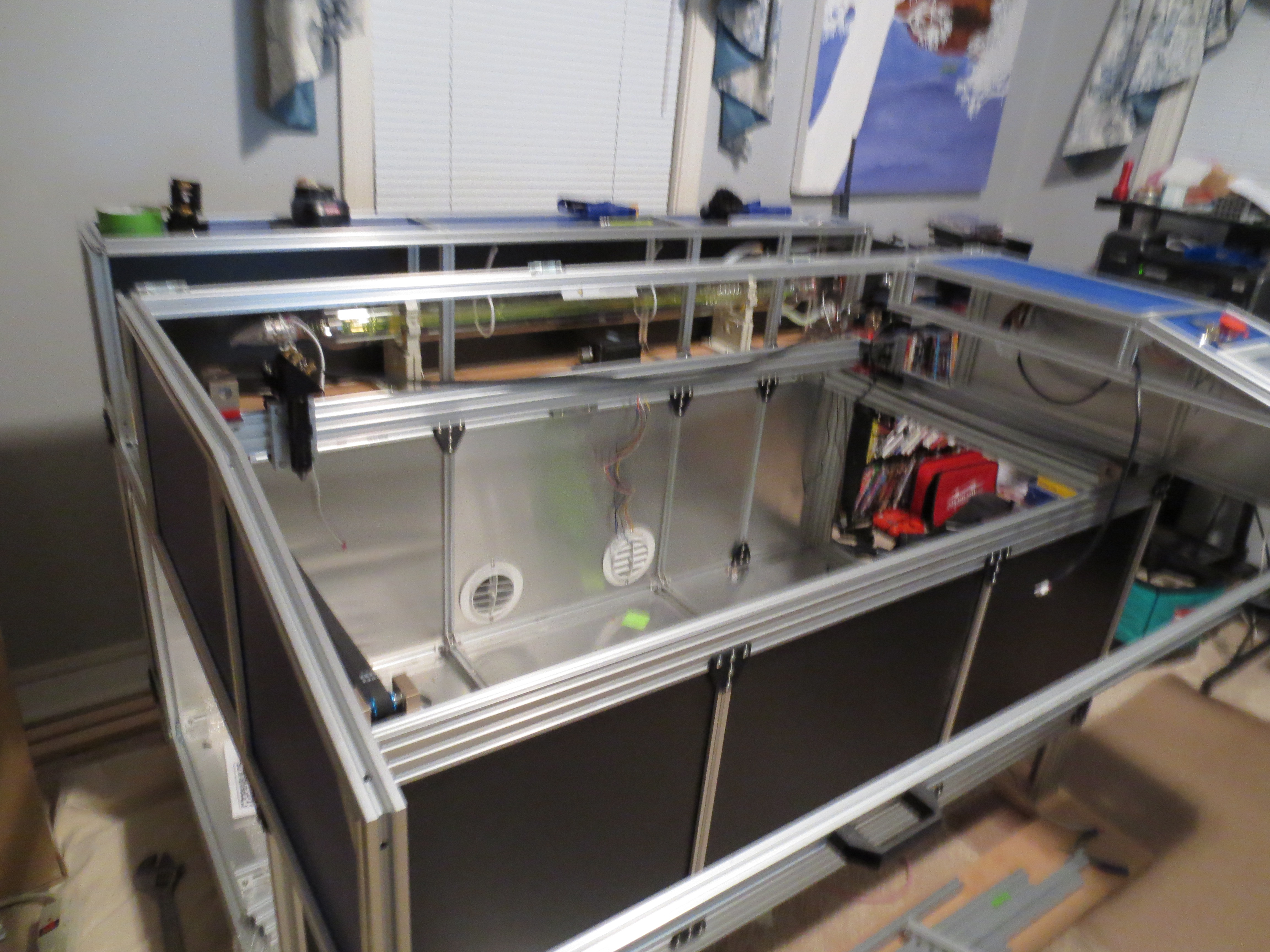
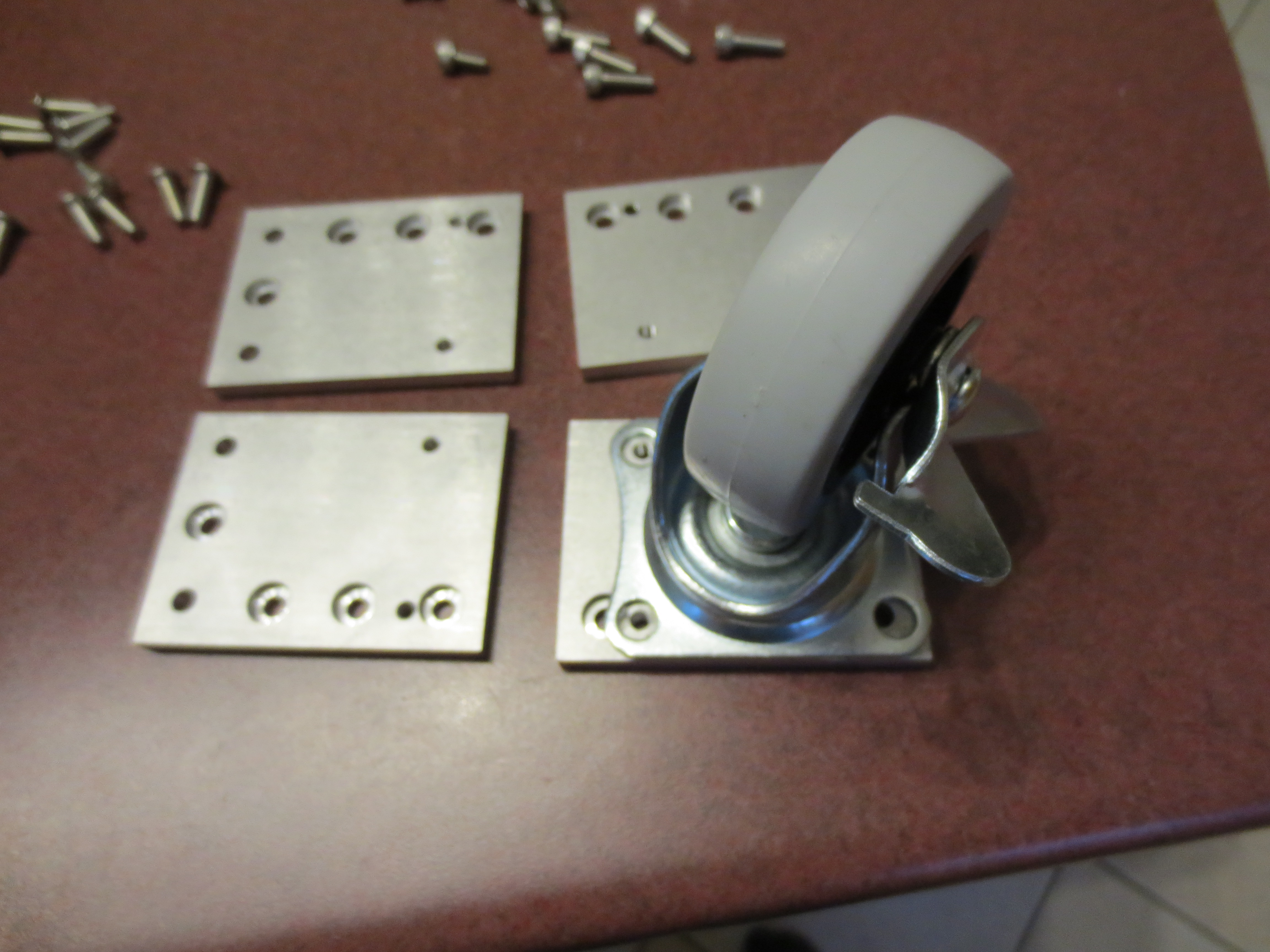
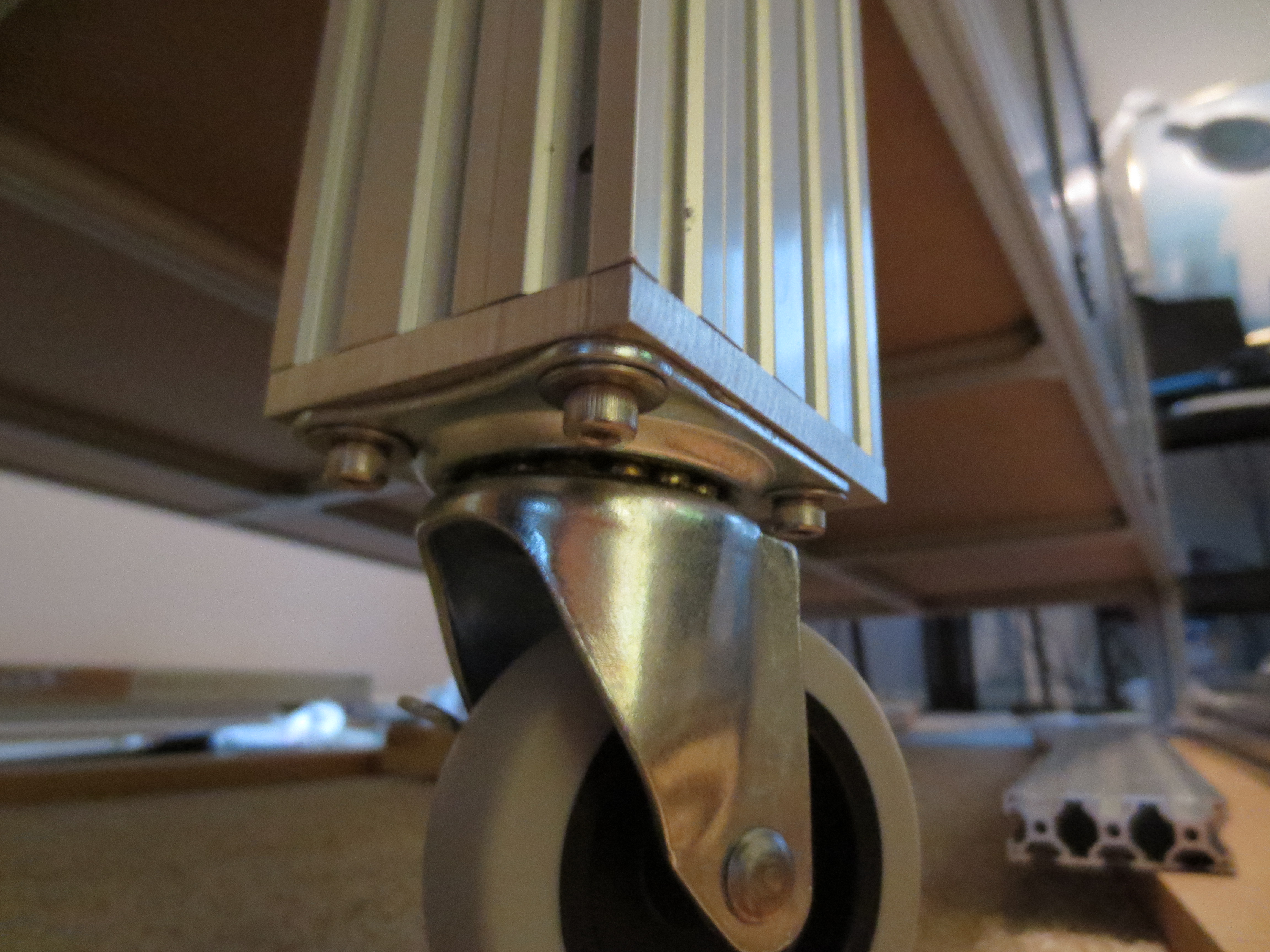
Wheels
Wheels were needed because the Laser Cutter weighs about 250-300lbs!!!
Linear Slides
I started out with using VSlot aluminum and poly then eventually steel VSlot bearings as linear slides…
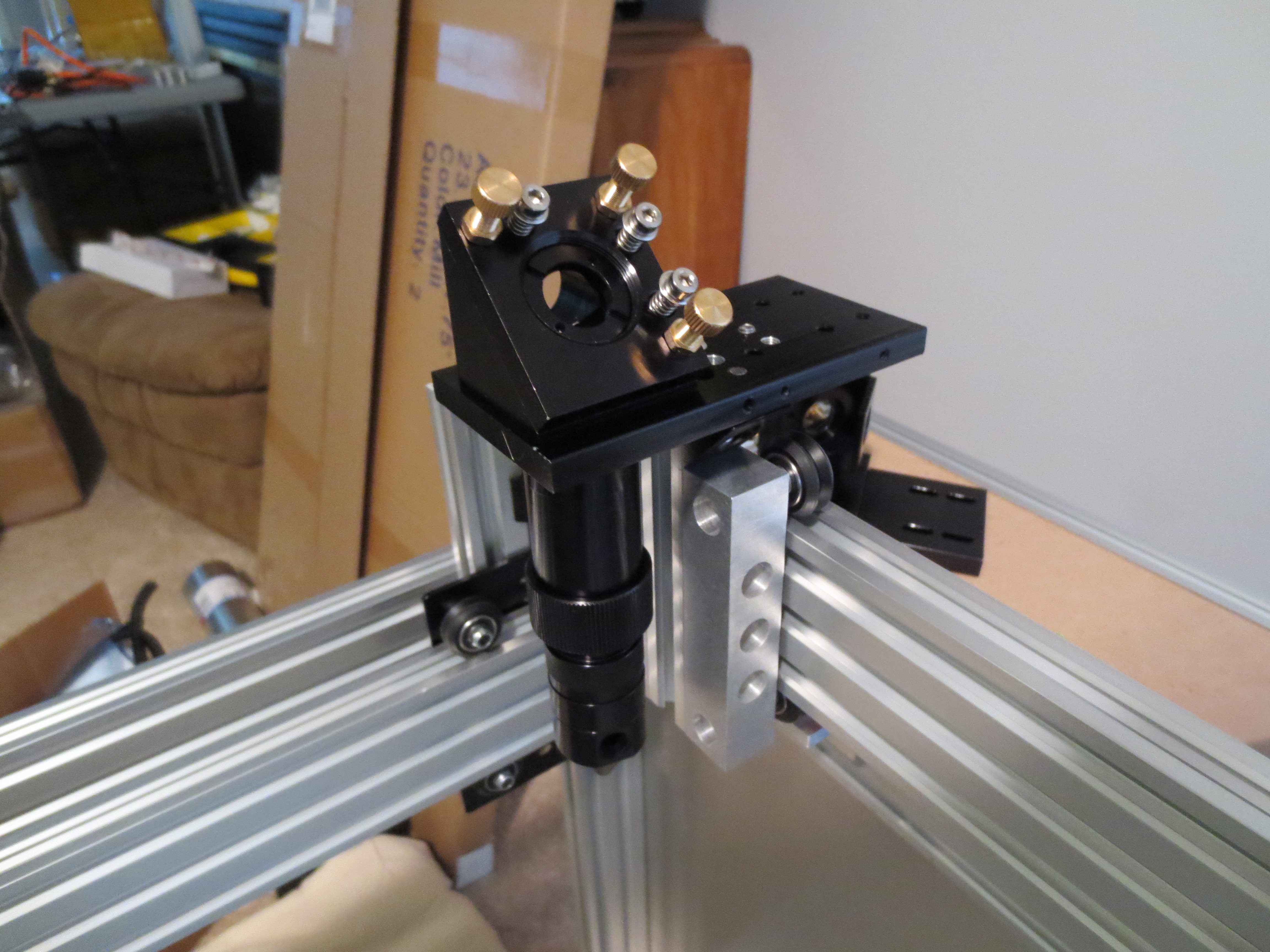
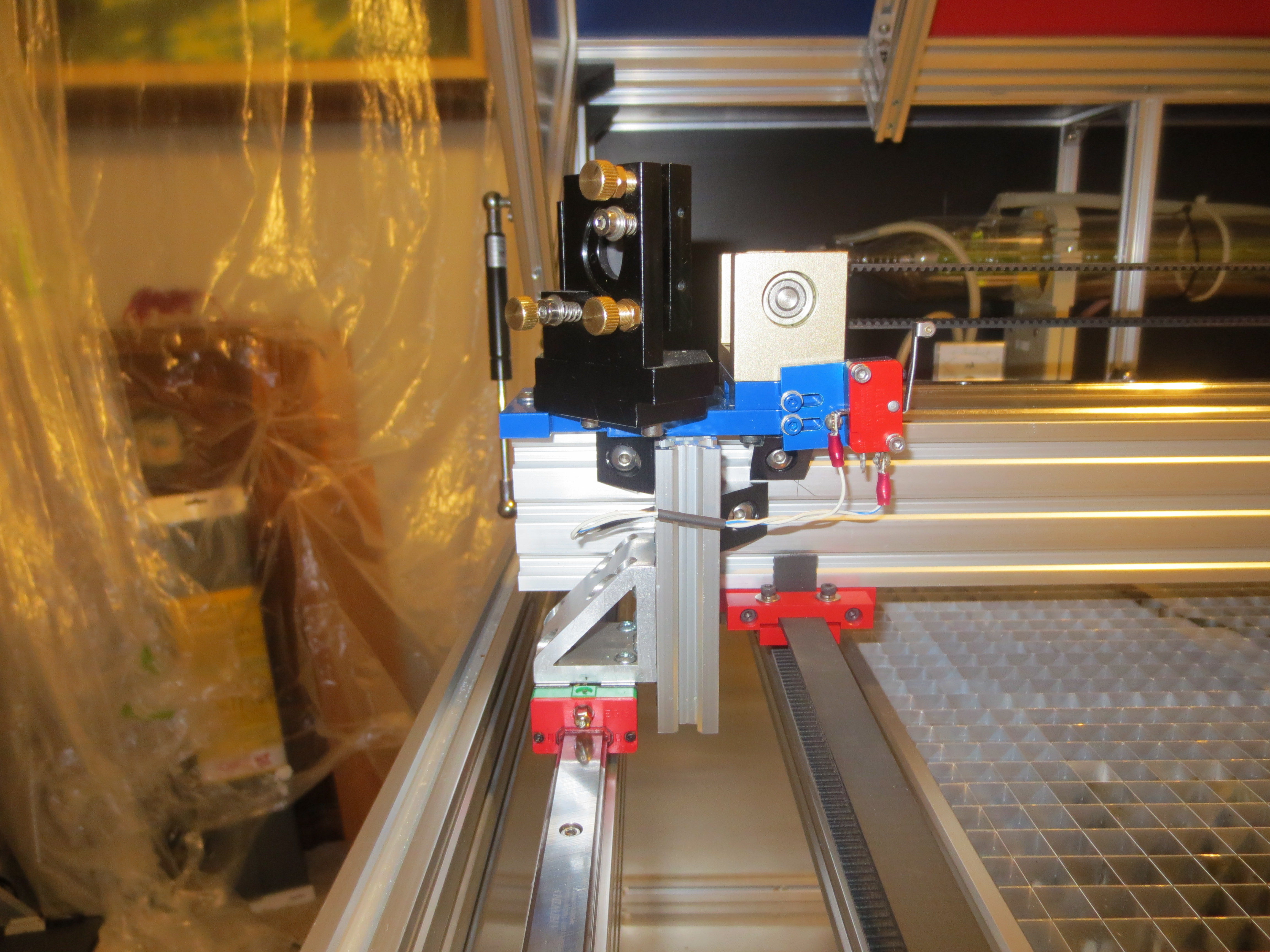
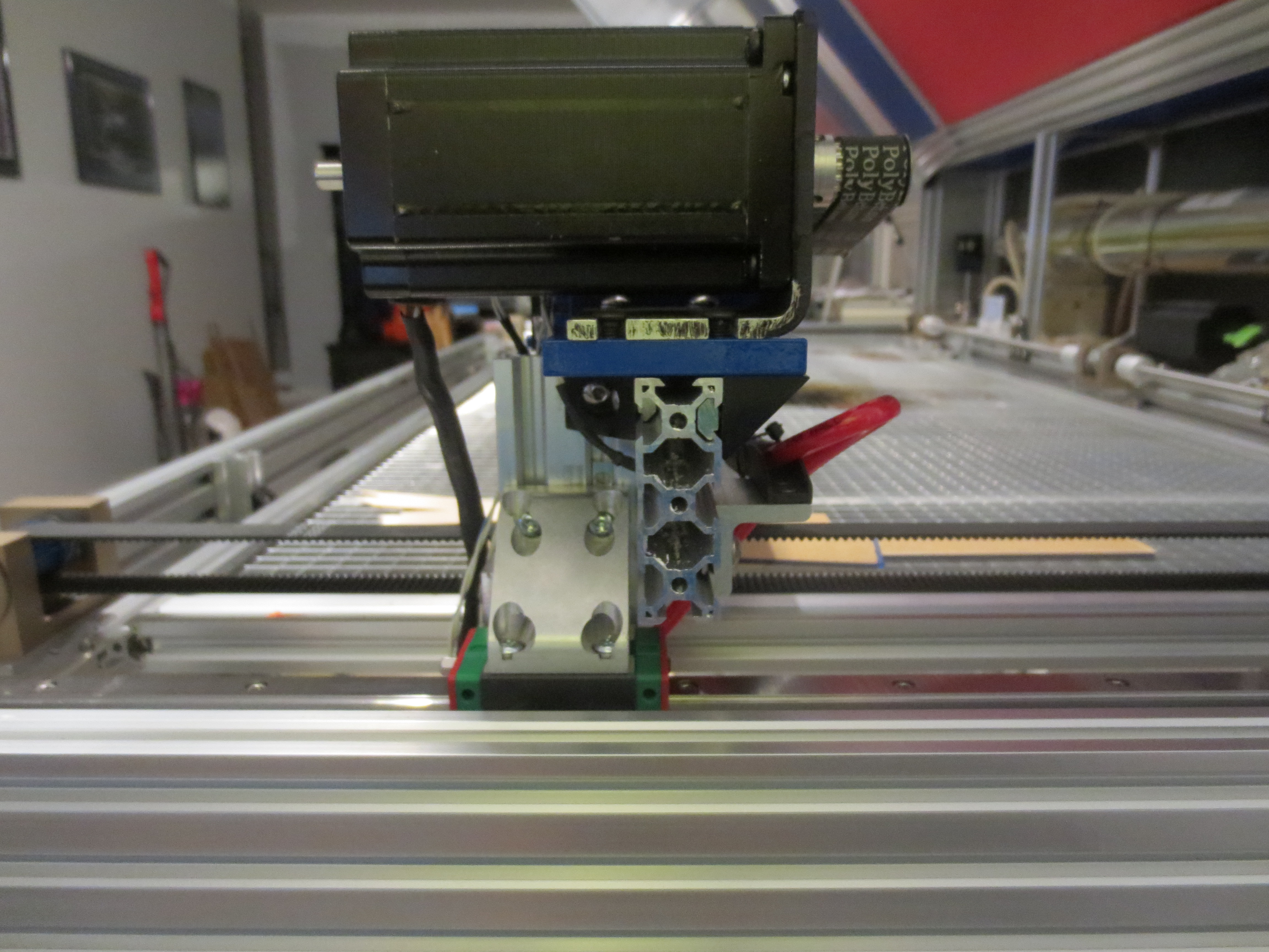
I migrated from poly bearings to steel VSlot bearings to tighten up the control movements along each axis. Eventually I purchased some real linear bearings and really tightened up the movements of the laser head. The new linear slides were added which meant new X & Y Axis components for the laser head, pulleys and mirror mounts. The X-Axis rail is ~1300mm EG15. The X-Axis has one EGH15CA block (bearing). The blue laser head mount was custom made using the original as a model, adjusting for mirror height and X-Axis parallel offset.
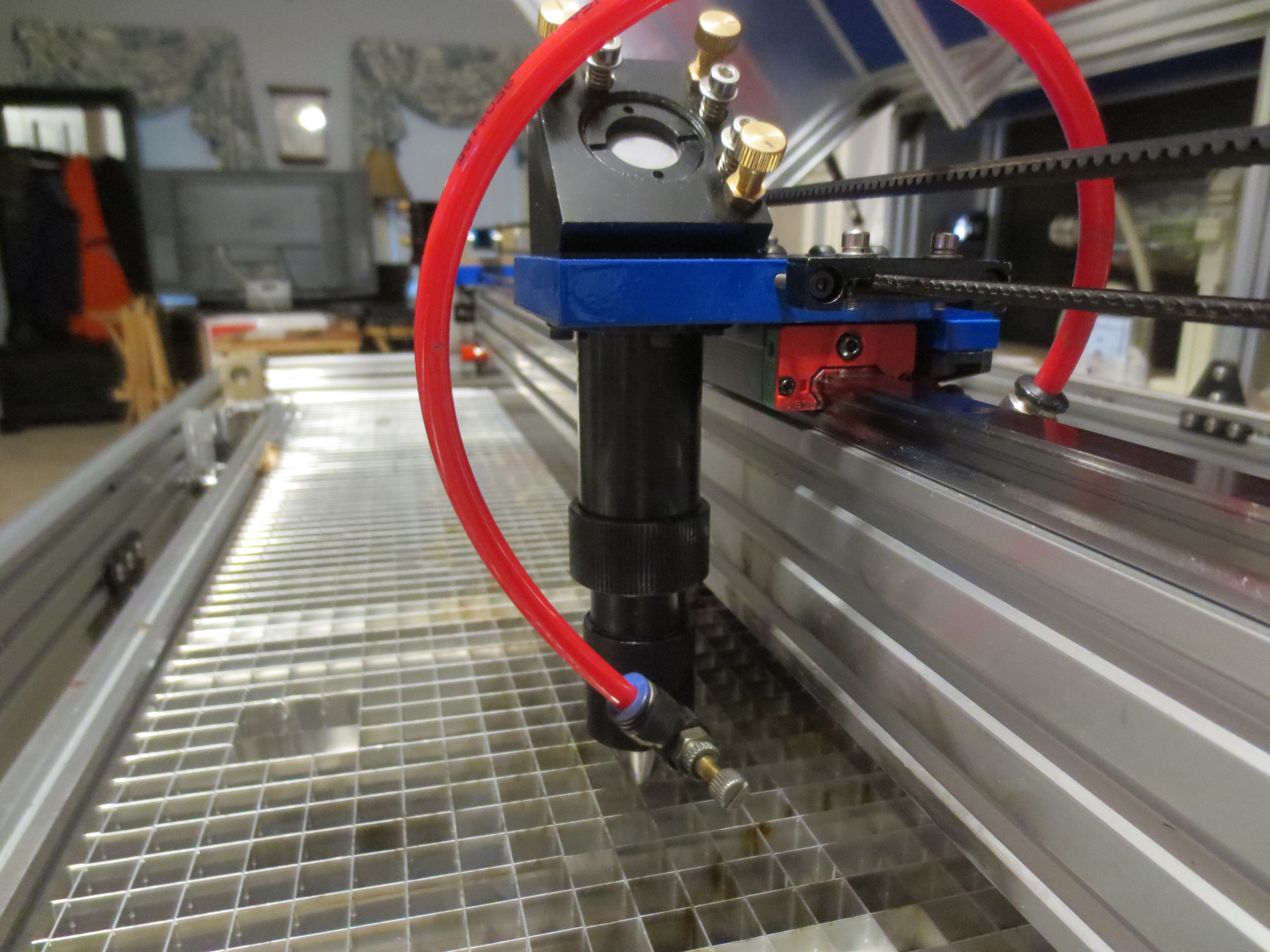
The Y-Axis has one EGH15CA on the left and one on the right. The angle brackets were machined from “2020 Aluminum” on EBay. The blue mirror mounting plate, blue pulley mounting plate and blue limit switch mount were machined from scrap aluminum. There is a channel machined into the mounting plates that straddle the linear slide that allow for course positioning of the mirror. I used T-Slot aluminum to allow for up-down alignment of the X/Y-Axis movement to align the belts and mirror position.